UltimaSerial


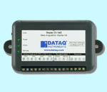
![]() Download UltimaSerial now if you are starting a
new project! It supports USB-based powerful data loggers DI-148, DI-158,
DI-710 & DI-715B
Download UltimaSerial now if you are starting a
new project! It supports USB-based powerful data loggers DI-148, DI-158,
DI-710 & DI-715B![]()
UltimaSerial provides a lot of powerful functions to explore the application of DI-150RS/151RS/190/194/194RS/195B serial data acquisition devices.
In the VB sample programs installed along with UltimaSerial control, most of these properties, methods and events are addressed.
Extra Properties:
PreTriggerLength (integer) specifies the number of scans before the trigger point, 0 to 8000 scans can be specified (default: 100). The sum of PreTriggerLength and PostTriggerLength should not be higher than 8000.
Valid PreTriggerLength: 0 to 8000
PostTriggerLength (integer) specifies the number of scans after the trigger point, 1 to 8000 scans can be specified. 0 is for free-run after the trigger condition is met. (default: 100). The sum of PreTriggerLength and PostTriggerLength should not be higher than 8000.
Valid PostTriggerLength: 0 to 8000, where 0 means infinity.
AcquisitionMode (integer) specifies the mode of acquisition, which includes unconditional, trigger on rising edge of an analog or digital input, trigger on falling edge of an analog or digital input, acquire when signal above a threshold level of an analog input, acquire when signal below a threshold level of an analog input, acquire when transitional counter reaches a predefined value, etc. A trigger event will be fired when the trigger condition is met.
Valid Acquisition Mode:
0 = NoCondition (default)
1 = OnEdgeLow2High
2 = OnEdgeHigh2Low
3 = WhenAboveLevel
4 = WhenBelowLevelSquareWaveOutput (Boolean) When set, a pre-programmed square wave will be output on a pre-defined Digital channel (D2 for DI-194), which can be fed back to an analog channel for demo purpose. Sorry, but the pattern of the square wave cannot be changed.
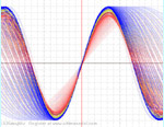
SmoothScrolling (Boolean) When set, a higher speed monitoring process will be used to acquire the data so that the waveform can be plotted a lot more smoother.
Due to the restriction of VB IDE, this feature should only be used outside of VB IDE, as complied EXE application, after the program is fully developed. For the same reason, this feature should not be used in Excel VBA. I am working to take care this issue.
TriggerChannel (integer) specifies the channel where the trigger condition takes place, which includes all available analog channels, digital channels and transitional event counters.
Valid Trigger Channel:
0 = AnalogCh1
1 = AnalogCh2
2 = AnalogCh3
3 = AnalogCh4
100 = Digital0
101 = Digital1
102 = Digital2
200 = L2HCounter0
201 = L2HCounter1
202 = L2HCounter2
300 = H2LCounter0
301 = H2LCounter1
302 = H2LCounter2TriggerStatus (integer) returns the states of trigger mode
Possible returns:
0 = Filling PreTrigger Buffer
1 = Waiting for initial state
2 = Waiting for level crossing
3 = Filling PostTrigger Buffer
4 = TriggerDoneTriggerLevel (integer) specifies the threshold for trigger mode (default: 0)
Valid numbers:
Analog channels: -32768 to 32768
Digital channels: 0 and 1
EventCounters: Any positive numbersMaskOutDigitalBits (Boolean) when set, the digital bits will be masked out from the data stream (default: false)
Extra Methods:
int DigitalInput (int channel) returns the states of digital channels
Valid channel: 0, 1 and 2.
DI-190 has two digital channels (0, 1) labeled as Dig 0 & Dig 1
DI-151RS has two digital channels (0, 1) labeled as Dig 0 & Dig 1
DI-154RS has two digital channels (0, 1) labeled as D0 & D1 (D2 is always a square wave output)
DI-194/194RS has three digital channels (0, 1, 2) labeled as D0, D1 & D2
DI-195B has one digital channel (0) labeled as DINvoid TransitionCounter (int channel, int edge) returns the contents of transitional counters.
Valid channel: 0, 1 and 2 for digital channel 0, 1 and 2
Valid edge: 0, 1, where 0 is low-to-high transition, 1 is high-to-low.Using the digital channels of the device as a transitional counter, we have:
DI-190 has two low-to-high transitional counters, and two high-to-low transitional counters
DI-151RS has two low-to-high transitional counters, and two high-to-low transitional counters
DI-154RS has two low-to-high transitional counters, and two high-to-low transitional counters
DI-194/194RS has three low-to-high transitional counters, and three high-to-low transitional counters
DI-195B has one low-to-high transitional counters, and one high-to-low transitional countersvoid ResetCounter (int channel, int edge) resets a specified transitional counter
Valid channel: 0, 1 and 2 for digital channel 0, 1 and 2
Valid edge: 0, 1, where 0 is low-to-high transition, 1 is high-to-low.int AnalogInput (int channel) returns the immediate reading from an enabled analog channel. You must use the ChannelCount property to enable the appropriate channel before you can invoke this method to get the readings from a specified channel. For example, to read from channel 0, 1, 2 and 3 of DI-194, you must have ChannelCount=4, also you must use the Key to enable multiple channel setting on the DI-194.
Valid channel: 0, 1, 2 and 3.
DI-190 has two analog channels (0, 1)
DI-150RS has two analog channels (0, 1)
DI-151RS has two analog channels (0, 1)
DI-154RS has four analog channels (0, 1, 2 and 3)
DI-194 has four analog channels (0, 1, 2 and 3)
DI-195B has two analog channel (0)
Max/Min Readings of the duration for UltimaSerial (version 2)
To catch the Maximum reading of a specified channel in the duration of the test (from the moment Start method is invoked to the moment of this method is invoked), add 1000 to the valid channel count mentioned above. i.e. 1000, 1001, 1002 and 1003
To catch the Minimum reading of a specified channel in the duration of the test (from the moment Start method is invoked to the moment of this method is invoked), add 2000 to the valid channel count mentioned above. i.e. 2000, 2001, 2002 and 2003
To convert the AD Readings to voltage (assuming you are using -10 to +10V input range, which is the default for most of the serial devices):
For 12-bit devices like DI-195B, DI-190, DI-150RS, DI-151 and DI-154RS:
Voltage = 10 * (ADReading >>4)/2048
where >>4 means to shift the data to the right for 4 bits.
For 8-bit devices like DI-194:
Voltage = 10 * (ADReading >>8)/128
where >>8 means to shift the data to the right for 8 bits.
For 10-bit devices like DI-194RS:
Voltage = 10 * (ADReading >>6)/512
where >>6 means to shift the data to the right for 6 bits.
If you don't mind the little error caused by the integer calculation, you can always use:
Voltage = 10 * ADReading/32768
variant GetDataFrame (int Count) returns the most recent specified number of data frames as acquired by the control to a variant without affecting the continuity of the data stream. One frame is equivalent to one sample of each active channel. Click here to find out how to extract the data from the variant.
For example: UltimaSerial.GetDataFrame Count
Variables: Count is an integer and defines the number of scans you are requesting. The maximum number of scans you can request is 8,000.int GetDataFrameEx (short * Array, int Count) returns the most recent specified number of data frames as acquired by the control to an integer array without affecting the continuity of the data stream. One frame is equivalent to one sample from every active channel. GetDataFrameEx returns binary data. If you enable more than one channel, you will have to sort out the data for each channel yourself. The order of data points is: Ch1, Ch2, Ch1, Ch2, Ch1, Ch2, .... (assuming you enable two channels)
For example:: UltimaSerial.GetDataFrameEx A(0),Count
A(0) is a pointer to the 16-bit integer array, A. Count, an integer, is the number of data points, not scans, that you are requesting (30,000 maximum). The data will be aligned with the first channel.To convert the AD Readings to voltage (assuming you are using -10 to +10V input range, which is the default for most of the serial devices):
For 12-bit devices like DI-195B, DI-190, DI-150RS, DI-151 and DI-154RS:
Voltage = 10 * (ADReading >>4)/2048
where >>4 means to shift the data to the right for 4 bits.
For 8-bit devices like DI-194:
Voltage = 10 * (ADReading >>8)/128
where >>8 means to shift the data to the right for 8 bits.
For 10-bit devices like DI-194RS:
Voltage = 10 * (ADReading >>6)/512
where >>6 means to shift the data to the right for 6 bits.
If you don't mind the little error caused by the integer calculation, you can always use:
Voltage = 10 * ADReading/32768
MapErrorMessage (int errorcode) as string maps the error code returned by the control to a brief description of the problem. Here are the map if you want to do it yourself:
-1: Invalid device name
-2: Invalid COMM port
-3: Invalid channel count. Original channel count is unmodified
-4: Sample out of possible range
-5: Invalid channel count. Channel count is changed to 1
-10: Trigger Level too high, and will be changed to 32767
-11: Trigger Level too low, and will be changed to -32768
-12: This trigger mode does not use pre- nor post- trigger length
-13: Unsupported trigger mode
-14: Unsupported trigger channel
-15: This channel does not support alarm setting
-998: Failed to communicate to the device
-999: Failed to send key to DI-194
-1000: Invalid key to DI-194! Channel Count changes to 1
-3000: Failed to create monitoring process, please poll the data from VB Timer function
-800: COM port is not available
SetLimitLine (int type, int threshold) specifies the type of monitoring and threshold to be used in LimitLine operation. When a specified channel passes the limit line, event LimitLine will be fired. Each channel can have two limit lines, one for high limit and one for low limit.
Valid type:
0 = AnalogChannel1Below
1 = AnalogChannel1Above
2 = AnalogChannel2Below
3 = AnalogChannel2Above
4 = AnalogChannel3Below
5 = AnalogChannel3Above
6 = AnalogChannel4Below
7 = AnalogChannel4Above
Extra Events:
GapInDataStream indicates a gap is detected in the data stream
Trigger (Timer as string) returns the closest moment of triggering the monitoring process can determine.
LimitLine (Time as string, Channel as integer) indicates a pre-specified LimitLine is passed.
In the VB sample programs installed along with UltimaSerial control, most of these properties, methods and events are addressed.
Last update: 02/29/12
Copyright: 2000-2005 www.UltimaSerial.com