7035
Menu Name Appeared under WinDaq->View->Add-ons
Dynamometer
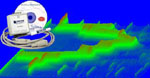
Dynamometer (Dyno) Data Acquisition Recorder
Dynamometer Recorder adds Torque and Speed channels generated by dynamometers to Windaq files in real-time. Due to its low popularity, it is normally installed as a hidden add-on. Please use Windaq Add-on Manager to add it to Windaq's menu if you wish to use itWith Windaq/Dyno recorder and data logger from Dataq, one can chart and record other critical parameters, such as temperature, pressure and air intake, along with torque and speed from your dynamometers in motor engine torque test so that you can better understand and adjust the performance.


Video demo of Dynamometer add-on
-
Applications
-
With Windaq/Dyno recorder and data logger from Dataq, one can chart and record other critical parameters, such as temperature, pressure and air intake, along with torque and speed from your dynamometers in motor engine torque test to better understand and adjust the performance.
-
-
Supported Devices:
DSP6000, DSP6001 and 6200 Dynamometer, Micro Dyne System, Model 6400 Torque Transducer Display, Model 3410 Torque Display -
Supported Dynamometers or Torque Displays
-
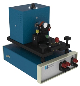
DSP6000 Dynamometer from Magtrol
-
DSP6001 Dynamometer from Magtrol
-
6200 Dynamometer from Magtrol
-
Micro Dyne System from Magtrol
-
Model 6400 Torque Transducer Display from Magtrol
-
Model 3410 Torque Display from Magtrol
-
-
Operating Systems:
Windows 7/Vista/XP/NT/Server 2008/2003/2000/98/Me, both 32 and 64 bit system
- To Use WinDaq Add-ons
-
Confirm WinDaq 3.16 or higher is installed on your computer
-
Install WinDaq add-ons.
-
Start WinDaq, and you will find the WinDaq add-ons integrated into Windaq->View->Add-ons menu (see the screen capture above).
-
Intelligent Channel Selection: Highlight/Select a channel in WinDaq and fire up the WinDaq add-on you wish, and the WinDaq add-on will use the selected channel as its default channel.
-
If channel index number is required for a WinDaq add-on, please enter the 0-based index to Windaq's scanlist. For example, if WinDaq has channel 3,4,6,7 enabled, one can enter 0 for channel 3, 1 for channel 4, 2 for channel 6 and 3 for channel 7.
-
Do not change WinDaq's configurations while WinDaq add-ons are running, or some add-ons may terminate.
-
Performance and Features
-
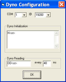
Custom configuration for dynamometer
-
Dyno Initialization contains the commands to set up Dyno: For example you can change dyno's torque and RPM ranges
-
Dyno Reading sends the request command to dyno at the rate defined in interval box: Some dyno requires read command for each pair of torque and RPM readings
-
The interval is defined as the absolute value of the number inside the interval text box
-
The minimum interval is dictated by the timer resolution of Windows.
-
Positive number: Most modern instruments would prefer this setting. For example, if the interval is 50 ms, the Dyno Reading command will be sent out every 50ms, OD<cr> ..... OD<cr> ..... OD<cr>, where .... represents the interval of 50ms
-
Negative number: The command strings will be sent out one character at a time at the predefined interval so that a slower instrument has enough time to process the command. For example, if the interval is 50 ms, the Dyno Reading command will be sent out one character at a time every 50ms, i.e, O....D....<cr>....O....D....<cr>....O....D....<cr>, where .... represents the interval of 50ms
-
Dyno allows user configuration to change its sensitivity and range. It is the user's responsibility to set up the Min/Max value for dyno channels, or the waveform maybe outside of the chart or too weak to plot
-
-
-
<cr> represents CR (carriage return) and <lf> represents LF (line feed).
Note: You will need to read dyno's user manual or contact the manufacturer to determine if you need CR or CR+LF to terminate a command line. According to one user's unverified account, Magtrol's command line should be ended by CR under RS-232 configuration instead of CR+LF even though the manual clearly indicates CR+LF.
-
-
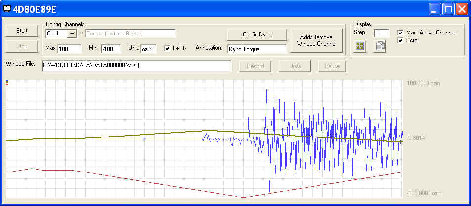
Combine Windaq channels and Torque and Speed channels generated by Dynamometer
-
Selectable sign: positive number for clockwise dynamometer shaft rotation Torque, negative for counterclockwise dynamometer shaft rotation, or the opposite
-
The directional input for Torque Transducer Display (Model 6400 and 3410) is ignored
-
Dyno allows user configuration to change its sensitivity and range. It is the user's responsibility to set up the Min/Max value for dyno channels, or the waveform maybe outside of the chart or too weak to plot
-
Support Pause/Resume
-
Commented Event Marker at resume
-
User annotation for each channel, including Torque and Speed channels
-
Auto increment for .WDQ file name
-
File size: up to 4GB
-
14-bit representation for Dyno channels
-
All important settings are retained between sessions
-
-
Chart Features
-
Plot all (up to 16) channels, which can be a mix of Torque and Speed channels and Windaq channels
-
To restore full dynamic range of a specific channel, click FS button
-
To space all waveform evenly, click "BestFit" button
-
To slow down the scrolling speed of the waveform, which will not affect file operation, increase the Step
-
Switch between limit/div legends, double click on the legends
-
Scroll or Sweep mode
-
Normal/Double width for the selected channel
-
Enable/Disable erase bar in sweep mode
-
Sizeable Chart
-
Use mouse wheel or buttons to zoom in/out
-
Copy button provides a copy of the waveform to the clipboard
-
Last update: 02/28/22
© www.UltimaSerial.com