Gauge
Gauge provides a programmable analog instrumentation gauge.
Applications
-
Calculated results based on readings from multiple channels, such as power consumption = V*I
-
Enlarged display
-
Warnings based on ring colors
Highlights
Intelligent Channel
Select: Highlight/Select a channel in WinDaq and invoke WinDaq->View->Add-ons->Magic
Meter, and it will use the selected channel as its default channel when it is not in calculated channel mode.
Move the mouse to the left edge of the display to reveal the configuration button.
- None: The last reading
- Average: Average all readings in the data window before presenting it
- Minimum: Display only the minimum reading within the data window
- Maximum: Display only the maximum reading within the data window
- RMS: Perform RMS for all readings within the data window
- AC RMS: Average all readings and use the result as offset. Remove the offset of all readings then perform RMS
- Calculated Channel with the following features:
-
Operators include: +, -, *, /, ^
-
Functions include: abs, floor, round, log, sqrt, ceil, log10, acos, asin, atan, sin, sinh, cos, tan, cosh, tanh
-
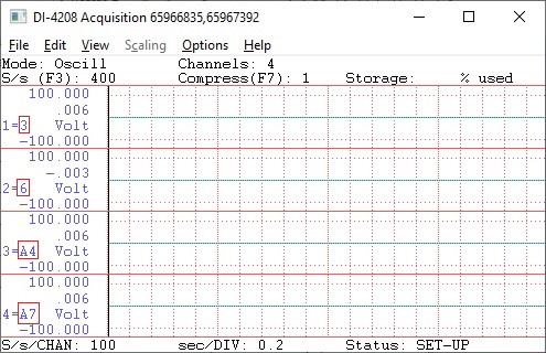
To use the reading from a channel, use CH notation, the channel number after this should match what you see in WinDaq. For example, CH3, CH6, CHA4 and CHA7 are available in the following WinDaq configuration
-
To use the data-window derived results, use MIN, MAX, AVE, FREQ, RMS and ACRMS to represent Min, Max, Average, Frequency, RMS, and ACRMS in the expression, i.e, CH1ACRMS returns the AC_RMS reading of channel 1 in the sampling window, CH2MIN returns the minimum reading of Channel 2 inside the sampling window.
The math equation must be valid even you don't plan to use it now
-
Programmable palette, gauge begin/end degree, min/max,
normal/high/low rang and display decimals for better visual effect
-
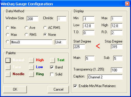
Min/Max retainers record the Minimum and Maximum readings since its started or the last time the Gauge was configured. Please note, since Gauge does NOT monitor every data point acquired by the device, the min/max only reflects all the values captured by Gauge addon.
-
To reset Min/Max retainers, enter Gauge Configuration and exit via OK button
-
Low/High are for extra visual support, for example to indicate a certain threshold or danger zones. In the above configuration screen shot, Low/High are outside of the Min/Max to remove the zone
T.D/R.D specify the number of digits after decimal point for the ticks on gauge face and reading in the lower center.
Start/Stop Degree defines the starting/ending point of the gauge arc
Main defines the number of major ticks on the gauge face
Sub defines the number of minor ticks between two major ticks
To Use WinDaq Add-on Gauge
Start WinDaq, and select (highlight) a channel
Invoke Windaq->View->Add-ons->Gauge, and the selected channel will be used as the default channel.
Do not change WinDaq's configurations while WinDaq add-ons are running
Configuration file
If you can't find it there, you may need to look in C:\Users\...\AppData\Local\VirtualStore\Windows
Last update: 07/22/24
© www.UltimaSerial.com