
Please use Digital and Alarm Output instead
WinDaq Add-on ID
7020
Menu Name Appeared under WinDaq->View->Add-ons
Alarm
To provide closed-loop control for WinDaq. It supports both simple logic and more complicated math expression modes. Due to its better replacement Digital Output is normally installed as a hidden add-on. Please use Windaq Add-on Manager to add it to Windaq's menu if you wish to invoke it from WinDaq Acquisition Software's add-on menu
-
Real Application
-
Robinson Helicopter company needs to conduct a rotor blade fatigue test, the normal signal is something like a sine waveform swing between 100 and 300 (real number is not used here to protect their IP), when the blade begins to show fatigue, the sine waveform will swing around a lower base line, say between 98 and 260, and at this point, the test must be stopped to prevent damage. To do that, they decide to monitor the mean value of the waveform over several cycles to determine when the test should be ended. First they establish the minimum acceptable level of the mean value using Magic Meter, which will be 200 if we use the numbers above, then equation (#min0+#max0)<0.95*200 is used to set the digital output to high, which in turn will trigger the switch to shut down the fatigue test.

-
-
Demo Video
-
Features
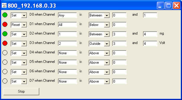
Simple Logic Mode
Support various combination of alarms
All settings are retainable
Both digital and visual alarm outputs
Monitoring rate up to 60Hz, depending on OS and workload
Conditions can be changed on the fly
Channel number is a 0-based index to Windaq's scanlist. For example, if Windaq has channel 3,4,6,7 enabled, one can enter 0 for channel 3, 1 for channel 4, 2 for channel 6 and 3 for channel 7. You may also set the channel to
None so that this alarm indicator will stay unchanged
ALL so that the alarm will be triggered when ALL channels meet the condition (see above)
ANY so that the alarm will be triggered when any one of the enabled channels meets the condition (see above)
Please configure the corresponding DIOs on DI-71x to outputs if you wish to use the digital outputs with DI-71x (Latest Windaq and DATAQ activex installation is required)
Due to the limitations of the hardware, when using with 720/730 USBs, please make sure Windaq's maximum sample rate doesn't exceed 100K, and the sample rate is less than 50K
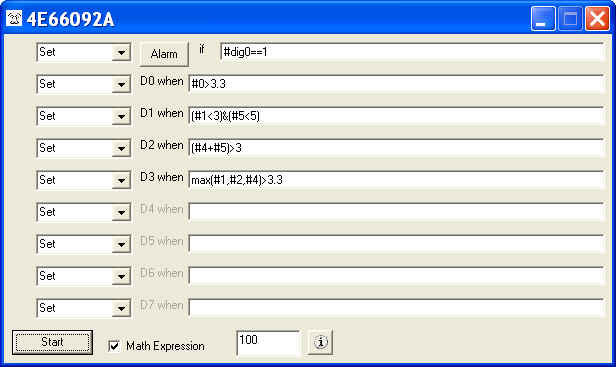
Math Expression Mode
Actions
Set: assign TRUE state based on the evaluation of the condition
Reset: assign FALSE state based on the evaluation of the condition
Force Set: force the output to TRUE unconditionally
Force Reset: force the output to FALSE unconditionally
Note: Majority of the devices' digital output is high TRUE, but DI-149's digital output is low TRUE but input is still high TRUE
For Audio alarm, TRUE plays the sound file
Math Expression
Support various combination of alarms resulted from math expressions based on readings from any enabled Windaq channel (see above image)
True math expression with many predefined operators and functions
Operators include: +, -, *, /, ^, %, &, |, !, >, >=, <, <=, !=, ==
Functions include: abs, floor, hex, round, if, avg, bin, log, sqrt, ceil, log10, sum, max, min, acos, asin, atan, sin, sinh, cos, tan, cosh, tanh
To use the reading from a channel, use #. For example, #0 is the reading from the first enabled channel in Windaq
Support non-English (United States) Regional and Language options.
Must read: The mystery of channel index!
Advanced Math
To use the data-window derived results, use #min, #max, #ave, #rms and #acrms to represent Min/Max/Ave/RMS/ACRMS in the expression, i.e, #acrms0 take the AC_RMS of channel 0.
The length of data window should be selected properly, especially in RMS or ACRMS mode, or wrong result may be generated. Hint, it should be multiple full cycles
Digital Input
To access individual digital input, use #dig0 to dig7 to access bit 0...7. Note, digital input must be enabled in Windaq's channel list. For example #dig1>0
To access all digital inputs, use #digx0. Note, digital input must be enabled in Windaq's channel list.
According WinDaq convention, the digital input range is from -128 to +127
For example #digx0==11
Audio Alarm
Allows selection of sound file (.wav)
Allow modification of alarm interval (in seconds)
Other Features
All settings are retainable
To use this feature, you should start the add-on from the SAME WinDaq logical channel. For example, highlight the second channel on WinDaq, start the add-on, set up the add-on then exit. Now the configuration is saved in a configuration file associated with second channel. You can have multiple configurations for the same device, each configuration associated with a different WinDaq logical channel. To recall the configuration stored associated with logical channel 2, highlight the channel on WinDaq, start the add-on.
The logical channel mentioned above is not the physical channel, it is the logical order of a physical channel listed in the channel selection box. For example, we have two WinDaq setups, one with physical channel 1,2,3,4,6,8, and the another with physical channel 6,7,9,10,14,15. If the add-on configuration is associated with the second logical channel, then highlighting physical channel 2 from the first setup then start the addon will be the same as highlighting physical channel 7 then start the addon.
Both digital and visual alarm outputs
Monitoring rate up to 60Hz, depending on device, OS and/or workload
Switch-able between math expression and simple logic like the old Alarm
Special Notes
Channel number is a 0-based index to Windaq's scanlist. For example, if Windaq has channel 3,4,6,7 enabled, one can enter 0 for channel 3, 1 for channel 4, 2 for channel 6 and 3 for channel 7.
Please configure the corresponding DIOs on DI-71x to outputs if you wish to use the digital outputs with DI-71x (Latest Windaq and DATAQ activex installation is required)
Due to the limitations of the hardware, when using with 720/730 USBs, please make sure Windaq's maximum sample rate doesn't exceed 100K, and the sample rate is less than 50K
Example:
Requirement
WinDaq has five channels enabled, Channel 1, Channel 3, Channel 4, Channel 6 and Channel 19
Three alarms are needed:
Digital Output 0 needs to be at high (TTL level) when Channel 1 is greater than 3.0 and Channel 19 is less than 2.1, low if the condition is not met
Digital Output 1 needs to be at low (TTL level) when the sum of Channel 3 and Channel 4 is greater than 19.9, high if the condition is not met
Digital Output 2 needs to be at low (TTL level) when the Digital input bit 0 is low and the RMS of Channel 3 is greater than 2, high if the condition is not met
Note: In the above statement regarding TTL level, we assume a high TRUE output device is what we are dealing with. DI-149's digital output is low TRUE but input is still high TRUE
Implementation
We will use math expression mode
Two equations will be used on D0 and D1 (Digital Output 0 and Digital Output 1)
Set D0 When #0>3.0 & #4<2.1
Since channel number used in the math expression is a 0-based index to Windaq's scanlist, Channel 1 becomes #0 and Channel 19 becomes #4
& is the logical operator AND
Set is the same as forcing the output HIGH for high TRUE device (DI-149's digital output is low TRUE but input is still high TRUE)
Reset D1 When (#1+#2)>19.9
Since channel number used in the math expression is a 0-based index to Windaq's scanlist, Channel 3 becomes #1 and Channel 4 becomes #2
Reset is the same as forcing the output LOW for high TRUE device (DI-149's digital output is low TRUE but input is still high TRUE)
Reset D2 When (#dig0==0) & (#rms1>2)
Since channel number used in the math expression is a 0-based index to Windaq's scanlist, Channel 3 becomes #1
Reset is the same as forcing the output LOW for high TRUE device (DI-149's digital output is low TRUE but input is still high TRUE)
Last update: 02/28/22
© www.UltimaSerial.com