|
WinDaq Add-ons |
|
Why WinDaq Add-ons?
WinDaq is the flagship data acquisition software package from DATAQ Instruments. It contains WinDaq data acquisition software and WinDaq Waveform Browser.
Our WinDaq Software Add-ons are designed to enhance the power of WinDaq software. With WinDaq add-ons, even the low-end products can employ many powerful functions found exclusively on expensive high-end packages, for example, SMS and email-enabled alarm, calculated trigger mode, derivative trigger mode, calculated channels, spectrum display and closed-loop control.
DATAQ Instruments Recommend Our WinDaq Add-ons to all WinDaq users
Supported Devices:
Any data acquisition device running WinDaq acquisition software, including: 
DI-149, DI-145, DI-148U, DI-154RS, DI-155, DI-158U/UP, DI-194RS, DI-195B, DI-400, DI-410, DI-500, DI-510, DI-700, DI-710, DI-715B, DI-718B, DI-718Bx, DI-720, DI-722, DI-730, DI-740, DI-750, DI-760, DI-785, DI-788, DI-1000TC, DI-1939, and DI-5001, Parallel port, USB, RS232 or Ethernet interface. 
Transonic's flow meters, RS232 interface. Dataforth's isoLynx SLX718, USB or Ethernet interface.
Featured Application: Email/Text Messaging (SMS)-enabled data acquisition
You are using WinDaq to monitor seismic activity, and you want to be notified as soon as the P-wave arrived so that you can prepare for the much more damaging S-wave that follows. To do that, you can use the Digital and Alarm Output or Remote Event Note Taker's Email/SMS link feature. Once the P-wave is identified, a message can be sent to your PC or smart phone immediately.
Operating Systems:
Windows 7/Vista/XP/NT/Server 2008/2003/2000/98/Me, both 32 and 64 bit system
Minimum Revision of WinDaq Acquisition Software:
3.16 and please make sure you have the latest WinDaq add-ons.
3.52 if you wish to employ the batch operation.
Latest Version of WinDaq Add-ons:
To Use WinDaq Add-ons
Confirm WinDaq 3.16 or higher is installed on your computer
Install WinDaq add-ons.
Restart WinDaq, and you will find the WinDaq add-ons integrated into Windaq->View->Add-ons menu (see the screen capture above).
Intelligent Channel Selection: Highlight/Select a channel in WinDaq and fire up the WinDaq add-on you wish, and the WinDaq add-on will use the selected channel as its default channel.
Do not change WinDaq's configurations while WinDaq add-ons are running, or some add-ons may terminate.
Here is the easy-print out version of this page
Retainable configuration
-
Many add-ons retain their configuration on exit
-
To use this feature, you should start the add-on from the SAME WinDaq logical channel. For example, highlight the second channel on WinDaq, start the add-on, set up the add-on then exit. Now the configuration is saved in a configuration file associated with second channel. You can have multiple configurations for the same device, each configuration associated with a different WinDaq logical channel. To recall the configuration stored associated with logical channel 2, highlight the channel on WinDaq, start the add-on.
-
The logical channel mentioned above is not the physical channel, it is the logical order of a physical channel listed in the channel selection box. For example, we have two WinDaq setups, one with physical channel 1,2,3,4,6,8, and the another with physical channel 6,7,9,10,14,15. If the add-on configuration is associated with the second logical channel, then highlighting physical channel 2 from the first setup then start the addon will be the same as highlighting physical channel 7 then start the addon.
WinDaq Add-ons
WinDaq Add-ons Listed in Alphabetical Order:
-
Add-on Batch Editor (ID=7040)
Create and Edit a batch startups for WinDaq add-ons. You can specify the channel each add-on uses.
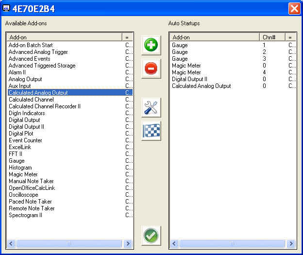
 add an
add-on from the available list to the auto startup group. Double
click on an item in the available add-ons group will render the
same result
add an
add-on from the available list to the auto startup group. Double
click on an item in the available add-ons group will render the
same result remove
the highlighted one from the auto startup group
remove
the highlighted one from the auto startup group change
the channel associated with the highlighted add-on in the auto startup group.
Double click on an item in the Auto Startup group will render the
same result. Please note, the channel has two possible meanings. Must read:
The mystery of channel index!
change
the channel associated with the highlighted add-on in the auto startup group.
Double click on an item in the Auto Startup group will render the
same result. Please note, the channel has two possible meanings. Must read:
The mystery of channel index!
- The logical channel being used by the Add-on, such as the FFT II.
- The retainable configuration # being used by the Add-on. For example, MagicMeter's Advanced Math module saves its retainable configuration to a file section associated with the channel number.
 test
drive the add-on highlighted in the auto startup group
test
drive the add-on highlighted in the auto startup group accept
and save the batch
accept
and save the batch
- Please note that the batch configuration is associated with each hardware configuration setup. For example, a batch configuration for DI-149 will NOT be applied to DI-720.
- Business Pro license is required if more than two add-ons
need to be started by Batch operation.
-
Add-on Batch Start (ID=7041)
There is NO GUI for this add-on. It starts the batch created by Add-on Batch Editor. If you have WinDaq rev 3.52, , you don't need to use this utility, for WinDaq will automatically invoke the batch operation. In the above example, three Gauges, two magic meters, digital output and calculated analog output will be started. Add-on Batch Start is normally installed as a hidden add-on. Please use Windaq Add-on Manager to add it to Windaq's menu if you wish to invoke it from WinDaq Acquisition Software's add-on menuBusiness Pro license is required if more than two add-ons are need to be started by Batch operation.
 How to config WinDaq to retain
its position and dimension?
How to config WinDaq to retain
its position and dimension? To fully take advantage of the batch operation, especially channel-related displays such as Magic Meter and Gauges, it would be desirable to have WinDaq come up at the same position and dimension whenever it is started.
The height and width can be retained by WinDaq->File->Save Default Setup
The position of the upper left corner may be specified in the following fashion
- Check WinDaq-> Edit-> Preferences-> Exit on Full
- Invoke WinDaq-> File-> Save Default Setup
- Uncheck WinDaq-> Edit-> Preferences-> Exit on Full
- Invoke WinDaq-> File-> Save Default Setup again
- To disable fixed positioning, move the window to the upper left corner and repeat steps 1 to 4
-
Add-on Manager (ID=7016)
Use this to manage the add-on menu, removing unused add-ons from the menu
Note:- The new add-on menu takes effect on the next start of WinDaq acquisition software
- The license takes effect on the next start of WinDaq add-ons
- Menu items are sorted in both list boxes
- Multiple selection is supported (see above image)
-
Advanced Event (ID= 7010)
Advanced Event adds audio capability to the commented event marks feature of WinDaq acquisition software.
Instead of typing in your text comment for events while recording data stream in Windaq, you may record your audio comment via the microphone of your PC!
Features of Advanced Event
- Support any microphone connected to your PC, as long as it is designated as default microphone input.
- Record hours of audio comment, and play it back in sync to the waveform with WWB Event Navigator
- Mark both the moment you start typing the text comment and the moment you push the insert button.
- If long (hours) audio comment is recorded, and the synchronization between comment and audio comment is important, due to WWB's time stamping method, it is recommended to start recording first, then pause and resume the recording right before inserting the audio comment.
- Please do not embed period in file name, for example, "My.Test.Wdq", or WWB Event Navigator will not be able to open it.
-
Until WinDaq enters record mode, you can't insert any
verbal/text comment
-
Advanced Analog Triggered Recorder (ID=7032)
This add-on uses calculated result to provide trigger mode for all Windaq-based instruments, including WinDaq Starter kits
- Advantage and Applications
- Huge pre- and post- trigger buffer
- Industry-first Analog Derivative Trigger Mode, e.g. dV/dt>30. For example, one can trigger on a glitch riding on a slow moving signal swinging from rail to rail
- Trigger on combination of conditions, e.g. Channel 1>0.2 and Channel 2 <3. This is especially important in test that has multiple variables
- Analog Calculated Trigger Mode, e.g. Channel 1 * Channel 2 >40. For example, the power consumption based on the readings of voltage and current
- Provide trigger mode for all Windaq-based instruments, including WinDaq Starter kits.
 provides direct Excel link for Business
Pro License users
provides direct Excel link for Business
Pro License users
- Supports both 32-bit and 64-bit version Microsoft Excel
- You need full version of Microsoft Excel to use this feature. Click here to learn more about this requirement.
- Live streaming to Excel when trigger condition is met!
- Please make sure the sum of pre-trigger length and post-trigger length does not exceed your Excel's row limit
- Recording capability
- Auto increment for WinDaq file name
- Up to 8000 event-marked trigger captures per file
- File size: up to 4GB
- Performance and Features
- Maximum throughput rate depends on many factors.
- If there is no trigger for more than 3 + (pre-trigger period) + (post-trigger period) seconds, the display turns into free-run mode, just like a real scope's trigger mode
- Here are some suggestions on how to maximize the
performance:
- Enable as few WinDaq channels as possible.
- If the sample rate is a constant, use a constant in the equation instead of referring to #@
- All important settings are retained between sessions
- Trigger States and their indicators
- Blue: Filling up pre-trigger buffer
- Yellow: Waiting for condition to be FALSE first
- Green: Waiting for condition to be TRUE
- Red: Filling up post-trigger buffer
- Chart Features
- Plot all (up to 16) WinDaq channels
- Sizeable Chart
- Trigger Indicator: "|<<<"
- Use mouse wheel or buttons to zoom in/out
- True math expression with many predefined operators and
functions
- Must read: The mystery of channel index!
- Operators include: +, -, *, /, ^, %, &, |, !, >, >=, <, <=, !=, ==
- Functions include: abs, floor, hex, round, if, avg, bin, log, sqrt, ceil, log10, sum, max, min, acos, asin, atan, sin, sinh, cos, tan, cosh, tanh
- To use the reading from a channel, use #n. For example, #0 is the reading from the first enabled channel in Windaq
- To access the sample rate, use #@.
- You can use earlier readings to form a more complicated
math expression. To do so, add a letter after #, and alphabet
order of the letter represents the delay, such as:
- #0 is the reading from channel 0
- #A0 is the reading from channel 0, one scan earlier
- #B1 is the reading from channel 1, two scans earlier
- Readings from up to 26 scans earlier can be used, for example, #Z0
- For example: use ( #0-#A0)*#@, or #0-#A0, to form a two-point derivative
- The math equation parser uses standard English (United
States) notation without the present of digital grouping symbol,
the decimal point must be "." (period) instead of ","
(comma). If your Regional and Language Setting is not English
(United States), you may need to adjust it
- Advantage and Applications
-
Advanced Triggered Storage (ID=7039)
Comparing to WinDaq's single-trigger counter part, this add-on uses calculated result to provide two trigger points for all Windaq-based instruments. For example, add a start trigger of "#0<7" and a stop trigger of "#0<5.1", it can be used to record a battery discharging curve like the one shown below
- Advantage and Applications
- Two trigger points based on calculated result, one for start, another for stop
- Trigger on combination of conditions, e.g. Channel 1>0.2 and Channel 2 <3. This is especially important in test that has multiple variables
- Analog Calculated Trigger Mode, e.g. Channel 1 * Channel 2 >40. For example, the power consumption based on the readings of voltage and current
- Recording capability
- Auto increment for WinDaq file name
- Up to 8000 event-marked trigger captures per file
- File size: up to 4GB
- Performance and Features
- Maximum throughput rate depends on many factors.
- Here are some suggestions on how to maximize the
performance:
- Enable as few WinDaq channels as possible.
- If the sample rate is a constant, use a constant in the equation instead of referring to #@
- All important settings are retained between sessions
- Trigger States and their indicators
- Green: Waiting for the start trigger
- Red: Recording
- Chart Features
- Plot all (up to 16) WinDaq channels
- Sizeable Chart
- Use mouse wheel or buttons to zoom in/out
- True math expression with many predefined operators and
functions
- Must read: The mystery of channel index!
- Operators include: +, -, *, /, ^, %, &, |, !, >, >=, <, <=, !=, ==
- Functions include: abs, floor, hex, round, if, avg, bin, log, sqrt, ceil, log10, sum, max, min, acos, asin, atan, sin, sinh, cos, tan, cosh, tanh
- To use the reading from a channel, use #n. For example, #0 is the reading from the first enabled channel in Windaq
- To access the sample rate, use #@.
- You can use earlier readings to form a more complicated
math expression. To do so, add a letter after #, and alphabet
order of the letter represents the delay, such as:
- #0 is the reading from channel 0
- #A0 is the reading from channel 0, one scan earlier
- #B1 is the reading from channel 1, two scans earlier
- Readings from up to 26 scans earlier can be used, for example, #Z0
- For example: use ( #0-#A0)*#@, or #0-#A0, to form a two-point derivative
- The math equation parser uses standard English (United
States) notation without the present of digital grouping symbol,
the decimal point must be "." (period) instead of ","
(comma). If your Regional and Language Setting is not English
(United States), you may need to adjust it
- Advantage and Applications
-
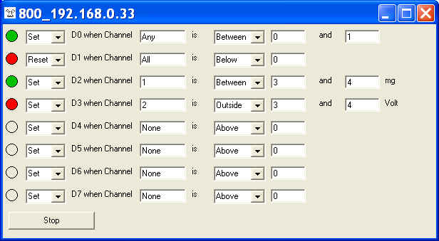
Alarm II (ID=7023)
This powerful utility provides closed-loop control for Windaq, with supports for both simple logic and more complicated math expressions. Due to its better replacement Digital Output II, Alarm II is normally installed as a hidden add-on. Please use Windaq Add-on Manager to add it to Windaq's menu if you wish to invoke it from WinDaq Acquisition Software's add-on menu
Simple Logic Mode
Math Expression Mode:
-
Actions
- Set: assign TRUE state based on the evaluation of the condition
- Reset: assign FALSE state based on the evaluation of the condition
- Force Set: force the output to TRUE unconditionally
- Force Reset: force the output to FALSE unconditionally
- Note: Majority of the devices output high TRUE, but DI-149 outputs low for TRUE
- For Audio alarm, TRUE plays the sound file
-
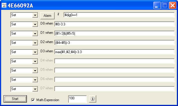
Math Expression
- Must read: The mystery of channel index!
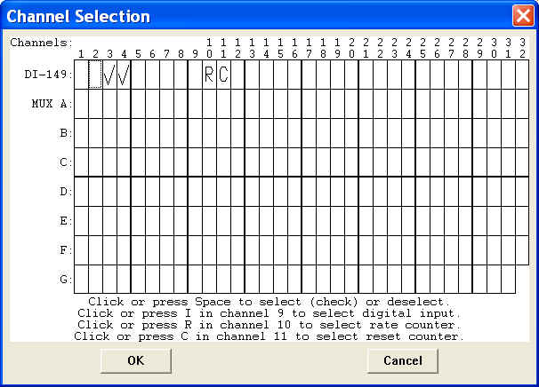
- Support various combination of alarms resulted from math expressions based on readings from any enabled WinDaq channel (see above image)
- True math expression with many predefined operators and functions
- Operators include: +, -, *, /, ^, %, &, |, !, >, >=, <, <=, !=, ==
- Functions include: abs, floor, hex, round, if, avg, bin, log, sqrt, ceil, log10, sum, max, min, acos, asin, atan, sin, sinh, cos, tan, cosh, tanh
- To use the reading from a channel, use #. For example, #0 is the reading from the first enabled channel in Windaq
- Support non-English (United States) Regional and Language options
- Advanced Math Expression
- To use the data-window derived results, use #min, #max, #ave, #rms and #acrms to represent Min/Max/Ave/RMS/ACRMS in the expression, i.e, #acrms0 take the AC_RMS of channel 0.
- The length of data window should be selected properly, especially in RMS or ACRMS mode, or wrong result may be generated. Hint, it should be multiple full cycles
- Application: Robinson Helicopter company needs to conduct a rotor blade fatigue test, the normal signal is something like a sine waveform swing between 100 and 300 (real number is not used here to protect their IP), when the blade begins to show fatigue, the sine waveform will swing around a lower base line, say between 98 and 260, and at this point, the test must be stopped to prevent damage. To do that, they decide to monitor the mean value of the waveform over several cycles to determine when the test should be ended. First they establish the minimum acceptable level of the mean value using Magic Meter, which will be 200 if we use the numbers above, then equation (#min0+#max0)<0.95*200 is used to set the digital output to high, which in turn will trigger the switch to shut down the fatigue test.
- Digital Inputs
- To access individual digital input, use #dig0 to dig7 to access bit 0...7. Note, digital input must be enabled in Windaq's channel list. For example #dig1>0
- To access all digital inputs, use #digx0. Note, digital
input must be enabled in Windaq's channel list.
- According to WinDaq convention, the range for digital channel is from -128 to +127
- For example #digx0==11
- Audio Alarm
- Allows selection of sound file (.wav)
- Allow modification of alarm interval (in seconds)
- Other Features
- All settings are retainable
- Monitoring rate up to 60Hz, depending on device, OS and/or workload
- Switch-able between math expression and simple logic like the old Alarm
-
Special Notes:
- Channel number is a 0-based index to Windaq's scanlist. For example, if WinDaq has channel 3,4,6,7 enabled, one can enter 0 for channel 3, 1 for channel 4, 2 for channel 6 and 3 for channel 7.
- This add-on and Digital output are mutually exclusive
- Due to the limitations of the hardware, when using with 720/730 USBs, please make sure Windaq's maximum sample rate doesn't exceed 100K, and the sample rate is less than 50K
- Please configure the corresponding DIOs on DI-71x to outputs if you wish to use the digital outputs with DI-71x
- Majority of the devices' digital output is high TRUE, but DI-149's digital output is low TRUE but input is still high TRUE
-
Example:
-
Requirement
- WinDaq has five channels enabled, Channel 1, Channel 3, Channel 4, Channel 6 and Channel 19
-
Three alarms are neeeded:
- Digital Output 0 needs to be at high (TTL level) when Channel 1 is greater than 3.0 and Channel 19 is less than 2.1, low if the condition is not met
- Digital Output 1 needs to be at low (TTL level) when the sum of Channel 3 and Channel 4 is greater than 19.9, high if the condition is not met
- Digital Output 2 needs to be at low (TTL level) when the Digital input bit 0 is low and the RMS of Channel 3 is greater than 2, high if the condition is not met
- Note: In the above statement regarding TTL level, we assume a high TRUE device (NOT DI-149!) is what we are dealing with
-
Implementation
- We will use math expression mode
-
Two equations will be used on D0 and D1 (Digital Output 0 and
Digital Output 1)
-
Set
D0 When #0>3.0 &
#4<2.1
- Since channel number used in the math expression is a 0-based index to Windaq's scanlist, Channel 1 becomes #0 and Channel 19 becomes #4
- & is the logical operator AND
- Set is the same as forcing the output HIGH for high TRUE device (not DI-149)
-
Reset
D1 When (#1+#2)>19.9
- Since channel number used in the math expression is a 0-based index to Windaq's scanlist, Channel 3 becomes #1 and Channel 4 becomes #2
- Reset is the same as forcing the output LOW for high TRUE device (not DI-149)
- Reset
D2 When
(#dig0==0) & (#rms1>2)
- Since channel number used in the math expression is a 0-based index to Windaq's scanlist, Channel 3 becomes #1
- Reset is the same as forcing the output LOW for high TRUE device (not DI-149)
-
Set
D0 When #0>3.0 &
#4<2.1
-
Requirement
-
Actions
- Analog Output (ID=7005)
Control outputs via the DACs of the device, including DI148/158/720/730/740, while WinDaq is running. Due to the limitations of the hardware, when using with 720/730 USBs, please make sure Windaq's maximum sample rate doesn't exceed 100K, and the sample rate is less than 50K
- Aux Input Indicator (ID=7037)
DI-720 series can have 8 extra digital inputs under most configurations. The extra digital inputs are from Aux Inputs. This is the visual indicators for Aux inputs. Digital channel must be enabled in WinDaq to use this add-on. Due to its low popularity, Aux Indicator is normally installed as a hidden add-on. Please use Windaq Add-on Manager to add it to Windaq's menu if you wish to invoke it from WinDaq Acquisition Software's add-on menu

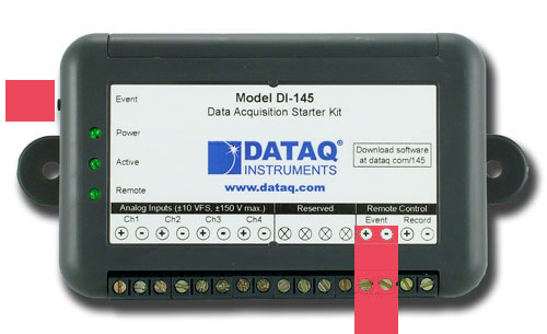
- The Aux Input port is the one on the right side of the front-panel
below. Please exercise the
same care like the standard digital inputs when using the Aux Inputs.
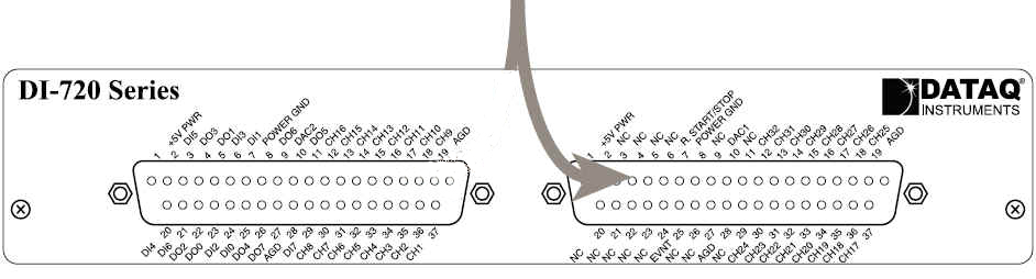
- Aux 0 at pin 25 (Also called Remote Event flag)
- Aux 1 at pin 6 (Also called Remote Storage control)
- Aux 2 at pin 24
- Aux 3 at pin 5
- Aux 4 at pin 20
- Aux 5 at pin 2
- Aux 6 at pin 21
- Aux 7 at pin 29
- Double-click on the indicators will enable/disable the sub
menu
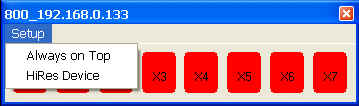
- Check "Always on Top" setting to keep the indicator on top of WinDaq
- Check "HiRes Device" if you are running HiRes (16-bit) WinDaq. If this setting is not setup accordingly, X0 and X1 may not reflect the real state of the Aux Input 0 and 1
- The Aux Input port is the one on the right side of the front-panel
below. Please exercise the
same care like the standard digital inputs when using the Aux Inputs.
-
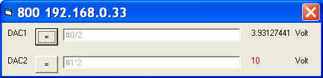
Calculated Analog Output (ID=7026)
Control analog outputs via the DACs of the device, including DI148/158/720/730/740, based on the result from a math equations from readings of enabled WinDaq channels. Due to the limitations of the hardware, when using with 720/730 USBs, please make sure Windaq's maximum sample rate doesn't exceed 100K, and the sample rate is less than 50K
- Monitoring rate up to 50Hz, depending on device, OS and/or workload. Great for analog closed-loop control
-
Math expressions are
retainable
- To bypass a DAC, enter NONE to the math expression. Once the DAC is bypassed, you can use the manual Analog Output to control it
- Must read: The mystery of channel index!
- Operators include: +, -, *, /, ^, %, &, |, !, >, >=, <, <=, !=, ==
- Functions include: abs, floor, hex, round, if, avg, bin, log, sqrt, ceil, log10, sum, max, min, acos, asin, atan, sin, sinh, cos, tan, cosh, tanh
- To access the sample rate, use #@
- Support non-English (United States) Regional and Language options
- To use the reading from a channel, use #n. For example, #0 is the reading from the first enabled channel in Windaq
-
You can use earlier readings to form a more complicated
math expression. To do so, add a letter after #, and alphabet
order of the letter represents the delay, Such as:
- #0 is the reading from channel 0
- #A0 is the reading from channel 0, one scan earlier
- #B1 is the reading from channel 1, two scans earlier
- Readings from up to 26 scans earlier can be used, for example, #Z0.
- For example: use ( #0-#A0)*#@ to form a two-point derivative
- The output will be checked against the DAC limits of the device. If min or max limit is exceeded, the result is represented by color code, red for higher than MAX, green for lower than MIN, see above image for reference.
-
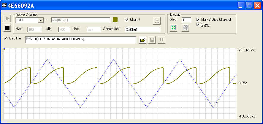
Calculated Channel Recorder II (ID=7029)
Calculated Channel Recorder II uses flexible math equation to record up to 16 calculated channel derived from Windaq-enabled channels in real-time, such as Power =Current * Voltage, a=dV/dt, and polynomial conversion.
-
Recording capability
- Up to 16 calculated channels
- Combine Windaq channels and calculated channels
- Support Pause/Resume
- Commented Event Marker at resume
- User annotation for each channel, including calculated and Windaq channels
- Auto increment for .WDQ file name
- File size: up to 4GB
- Applications
- Product of multiple channels, for examle, Watt = Voltage * Current
- Changing rate, for example,. A = dV/dT
- Non-linear sensor, for example, thermocouple's V-T curve is non-linear
- Performance and Features
- Maximum throughput rate depends on many factors. If only visual display is needed, please use Calculated Channel instead
- Here are some suggestions on how to maximize the
performance:
- Enable as few Windaq channels as possible
- Do not leave blank calculated channel(s) between assigned ones, for example, if two calculated channels are needed, assign them to Cal 1 and 2 and leave the rest blank instead of assigning them to Cal 1 and Cal 15 and leaving Cal 2 to Cal 14 blank
- If the sample rate is a constant, use a constant in the equation instead of referring to #@
- All important settings are retained between sessions, which
include
- MathExpression/Min/Max/Unit for each calculated channel
- Included Windaq Channels
- Chart scaling/offset for both calculated and Windaq channels
- Windaq file name/path
- Chart legend format
- Scroll/Sweep mode
- Erase bar setting
- Chart Features
- Plot all (up to 16) channels, which can be a mix of calculated channels and Windaq channels
- To restore full dynamic range of a specific channel, click FS button
- To space all waveform evenly, click "BestFit" button
- To slow down the scrolling speed of the waveform, which will not affect file operation, increase the Step
- Switch between limit/div legends, double click on the legends
- Scroll or Sweep mode
- Normal/Double width for the selected channel
- Enable/Disable erase bar in sweep mode
- Sizeable Chart
- Use mouse wheel or buttons to zoom in/out
- Copy button provides a copy of the waveform to the clipboard
- True math expression with many predefined operators and
functions
- Must read: The mystery of channel index!
- Operators include: +, -, *, /, ^, %, &, |, !, >, >=, <, <=, !=, ==
- Functions include: abs, floor, hex, round, if, avg, bin, log, sqrt, ceil, log10, sum, max, min, acos, asin, atan, sin, sinh, cos, tan, cosh, tanh
- To use the reading from a channel, use #n. For example, #0 is the reading from the first enabled channel in Windaq
- To access the sample rate, use #@.
- You can use earlier readings to form a more complicated
math expression. To do so, add a letter after #, and alphabet
order of the letter represents the delay, such as:
- #0 is the reading from channel 0
- #A0 is the reading from channel 0, one scan earlier
- #B1 is the reading from channel 1, two scans earlier
- Readings from up to 26 scans earlier can be used, for example, #Z0.
- For example: use ( #0-#A0)*#@, or #0-#A0, to form a two-point derivative
- The math equation parser uses standard English (United
States) notation without the present of digital grouping symbol,
the decimal point must be "." (period) instead of ","
(comma). If your Regional and Language Setting is not English
(United States), you may need to adjust it
-
Recording capability
-
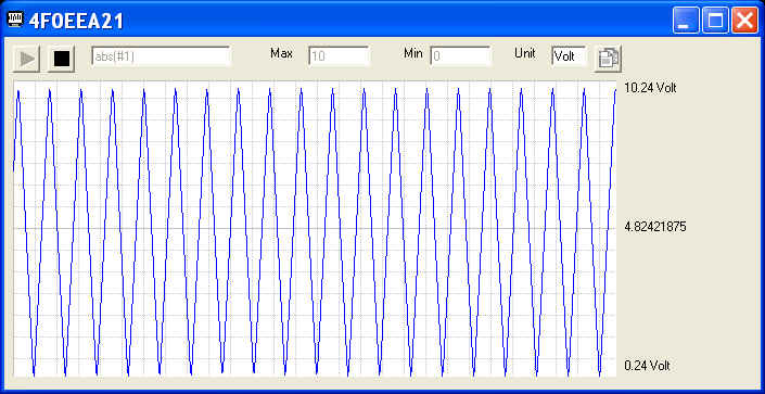
Calculated Waveform (ID=7024)
Use flexible math equation to generate a calculated waveform from Windaq-enabled channels in real-time, such as Power =Current & Voltage, a=dV/dt, and polynomial conversion.
-
Charting
- Use mouse wheel or buttons to zoom in/out
- Drag waveform up/down
- To restore full dynamic range of the chart, double click on the min/max notation next to the chart
- Sizeable chart
-
True math expression with many predefined operators and
functions
- Must read: The mystery of channel index!
- Operators include: +, -, *, /, ^, %, &, |, !, >, >=, <, <=, !=, ==
- Functions include: abs, floor, hex, round, if, avg, bin, log, sqrt, ceil, log10, sum, max, min, acos, asin, atan, sin, sinh, cos, tan, cosh, tanh
- To use the reading from a channel, use #n. For example, #0 is the reading from the first enabled channel in Windaq
- To access the sample rate, use #@.
-
You can use earlier readings to form a more complicated
math expression. To do so, add a letter after #, and alphabet
order of the letter represents the delay, Such as:
- #0 is the reading from channel 0
- #A0 is the reading from channel 0, one scan earlier
- #B1 is the reading from channel 1, two scans earlier
- Readings from up to 26 scans earlier can be used, for example, #Z0.
- For example: use ( #0-#A0)*#@ to form a two-point derivative
-
The math equation parser uses standard English (United
States) notation without the present of digital grouping symbol,
the decimal point must be "." (period) instead of ","
(comma). If your Regional and Language Setting is not English
(United States), you may need to adjust it
-
Charting
-
Digital Input Indicator (ID=7022)
Visual indicators for digital inputs
-
Monitor remote digital control flags like Remote Storage Control and Remote Event
-
Monitor standard digital inputs when the digital channel is enabled.
-
Not all digital inputs are available on every device/session and some devices overlap RS & Event with D0 and D1.
-
Double-click on the indicators will enable/disable the menu so that you can turn on/off "Always on Top" setting
-
The location and dimension of the add-on are retainable.
-
Note: for DI-194, WinDaq uses DI1 for both RS and Event, thus DI0 duplicates the value of DI1
-
- Digital Output
(ID=7006)
Control output via the digital output ports of the device (if available), including DI148/158/710/715/718BX/720/730/722/740.
Note:
- When using 7x0 USB, the Digital Outputs are on the expansion connector instead of the one with DOn labels
- Due to the limitations of the hardware, when using with 720/730 USBs, please make sure Windaq's maximum sample rate doesn't exceed 100K, and the sample rate is less than 50K
- Please configure the corresponding DIOs on DI-71x to outputs if you wish to use the digital outputs with DI-71x (Latest WinDaq and DATAQ activex installation is required)
- This add-on and Digital Output II and Alarm
are mutually exclusive
-
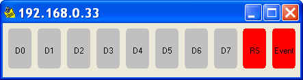
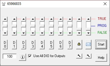
Digital and SMS/Email-enabled Alarm Output (ID=7036)
Digital and SMS/Email-enabled Alarm Output provides manual and auto-closed-loop control for WinDaq system, as well as Audio, SMS or Email alert when alarm is triggered
-
Actions
- Push the button D0...D7 to access the logical equation for the corresponding digital output.
- Push the button
 to access the logical equation for the SMS/Email alert.
 - Push the button
 to access the logical equation for the audio alert
 - Push the button
 under to configure the sound
file and alert time interval
under to configure the sound
file and alert time interval - Push the button
under
to configure the keep alive interval for SMS/Email periodical
reporting. Enter 0 to disable this feature
- Slides has three states
- TRUE: assign TRUE unconditionally
- FALSE: assign FALSE state unconditionally
- PROG: Set the output to TRUE if the logical equation for the corresponding channel renders TRUE
- Note
- For digital outputs, majority of the devices' digital output is high TRUE, meaning the output is above 2.4V. One exception: DI-149's digital output is low TRUE, meaning it is below 0.8V, but its input is still high TRUE
- For Audio alert, TRUE plays the sound file. FALSE stops the sound file
- For SMS/Email alert, TRUE generate periodical report if report interval is greater than 0. FALSE stops any SMS/Email alert.
- Keyboard operation
- Key 1,2,3,4,5,6,7,8,9 to set D0,1,2,3,4,5,6,7 and Alarm to PROG
- Key Q,W,E,R,T,Y,U,I,O to set D0,1,2,3,4,5,6,7 and Alarm to TRUE
- Key A,S,D,F,G,H,J,K,L to set D0,1,2,3,4,5,6,7 and Alarm to FALSE
- Global Key option, when enabled, one can force DOs to TRUE or
FALSE even when DigitalOutput II is not in focus
- Hold down Alt and Ctrl keys, then press Q, W, E, R, T, Y, U or I to set D0,1,2,3,4,5,6 or 7 to TRUE
- Hold down Alt and Ctrl keys, then press A, S, D, F, G, H, J or K to set D0,1,2,3,4,5,6 or 7 to FALSE
- The global keys stored in c:\windows\ultimaalarm.ini
can be reprogrammed
- Open c:\windows\ultimaalarm.ini and you will see multiple sections for different WinDaq configurations
- Under the section matching the device, you will see something like this
DoutTrueKey0=81
DoutFalseKey0=65
DoutTrueKey1=87
DoutFalseKey1=83
DoutTrueKey2=69
DoutFalseKey2=68
DoutTrueKey3=82
DoutFalseKey3=70
DoutTrueKey4=84
DoutFalseKey4=71
DoutTrueKey5=89
DoutFalseKey5=72
DoutTrueKey6=85
DoutFalseKey6=74
DoutTrueKey7=73
DoutFalseKey7=75
HKey0=17
HKey1=18 - The numbers are Microsoft Virtual Key codes. The HKey0 and HKey1 are the two hot keys to mark the commands, which are Ctrl and Shift by default.
- Change it to avoid conflict with other Windows application or add a new sets of command different Devices
- For example, if you have two 720s, assign 17 to HKey0 and HKey1 for the first WinDaq device, and 18 to HKey0 and HKey1 for the second WinDaq device. Thus, instead of using Alt+Ctrl, one can use Ctrl+QWERTYUI to set the digital output to high on device one, and Alt+QWERTYUI to set the digital output to high on device two..
- Math Expression
- Support various combination of alarms resulted from math expressions based on readings from any enabled WinDaq channel (see above image)
- True math expression with many predefined operators and functions
- Operators include: +, -, *, /, ^, %, &, |, !, >, >=, <, <=, !=, ==
- Functions include: abs, floor, hex, round, if, avg, bin, log, sqrt, ceil, log10, sum, max, min, acos, asin, atan, sin, sinh, cos, tan, cosh, tanh
- To use the reading from a channel, use #. For example, #0 is the reading from the first enabled channel in WinDaq
- Support non-English (United States) Regional and Language options.
- Advanced Math
- To use the data-window derived results, use #min, #max, #ave, #rms and #acrms to represent Min/Max/Ave/RMS/ACRMS in the expression, i.e, #acrms0 take the AC_RMS of channel 0.
- The length of data window should be selected properly, especially in RMS or ACRMS mode, or wrong result may be generated. Hint, it should be multiple full cycles
- Digital Inputs
- To access individual digital input, use #dig0 to dig7 to access bit 0...7. Note, digital input must be enabled in WinDaq's channel list. For example #dig1>0
- To access all digital inputs, use #digx0. Note, digital
input must be enabled in Windaq's channel list.
- According WinDaq convention, the digital input range is from -128 to +127
- For example #digx0==11
- Audio Alert
- Allows selection of sound file (.wav)
- Allow modification of alarm interval (in seconds)
- SMS/Email Alert
- Use SMS/Email Manager to configure it first
- Sends out email automatically when alarm is triggered
- Keep Alive email for periodical monitoring
- Three options
- TRUE: Only periodical SMS/Email output if it is enabled
- PROG: Alarm-triggered SMS/Email output, and periodical SMS/Email output if it is enabled
- FALSE: No SMS/Email output
- Other Features
- All settings are retainable
- Monitoring rate up to 60Hz, depending on device, OS and/or workload
- Special Notes
- Channel number is a 0-based index to Windaq's scanlist. For example, if Windaq has channel 3,4,6,7 enabled, one can enter 0 for channel 3, 1 for channel 4, 2 for channel 6 and 3 for channel 7.
- Please configure the corresponding DIOs on DI-71x to outputs if you wish to use the digital outputs with DI-71x (Latest Windaq and DATAQ activex installation is required)
- Due to the limitations of the hardware, when using with 720/730 USBs, please make sure Windaq's maximum sample rate doesn't exceed 100K, and the sample rate is less than 50K
- This add-on and Digital Output and Alarm are mutually exclusive
-
Actions
-
Digital Plot (ID=7038)
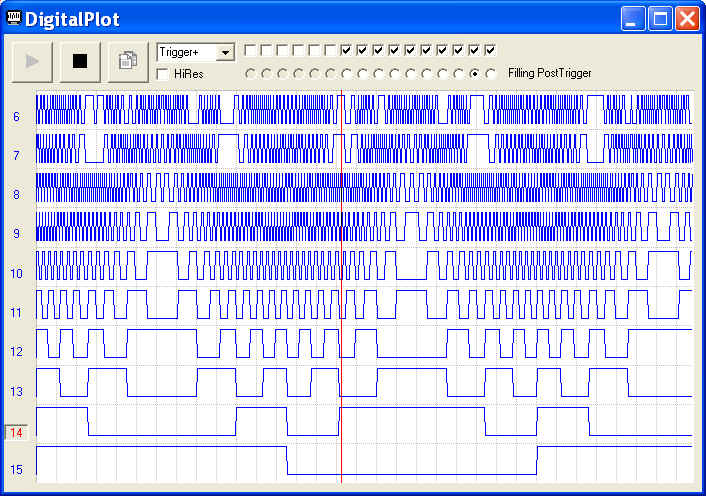
Features and Operation- Digital Plot generate the commonly-seen digital waveform
- DigitalPlot supports digital rising/falling edge trigger mode that works like a logic analyzer. Up to 200000 Hz sample rate can be achieved on DI-720USB, or 180000 Hz on DI-720Ethernet
- Digital Plot supports all 16 digital inputs from DI-720 series: eight from its
standard Digital Inputs,
the extra eight are from
Aux Inputs. The standard digital input is the the one on the left
side of the front-panel, and the Aux Input port is the one on the right side of the front-panel
below. Please exercise the
same care like the standard digital inputs when using the Aux Inputs.
- Aux 0 at pin 25 (Also called Remote Event flag)
- Aux 1 at pin 6 (Also called Remote Storage control)
- Aux 2 at pin 24
- Aux 3 at pin 5
- Aux 4 at pin 20
- Aux 5 at pin 2
- Aux 6 at pin 21
- Aux 7 at pin 29
- Bit assignment
- Bit 0...7: Aux 0...7
- Bit 8..15: Digital Input 0..7
- A
digital channel must be enabled in WinDaq to use this add-on.
- Uncheck the bits in BitMask to exclude them from the plotting. For example, if DI-149 is used, only 4 digital inputs from Bit 8 to 11 are available
- Four charting modes
- Scroll
- Sweep
- Trigger +: Trigger on rising edge, both the trigger channel and trigger length can be modified
- Trigger -: Trigger on falling edge, both the trigger channel and trigger length can be modified
- To modify the trigger
channel and trigger length
- Click on the chart to select trigger position
- Click on the channel annotation to select trigger channel
- Once the waveform is stopped, one can activate a cursor to examine the data
- Check "HiRes" if you are running HiRes (16-bit) WinDaq. If this setting is not setup accordingly, Bit0 and Bit1 may not reflect the real state of the Aux Input 0 and 1
-
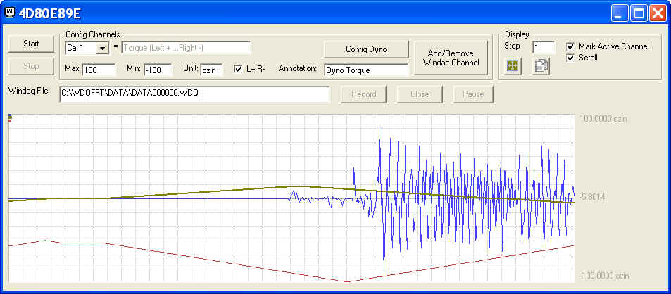
Dynamometer (Dyno) Data Acquisition Recorder (ID=7035)
Dynamometer Data Acquisition Recorder adds the Torque and Speed channels generated by dynamometers to Windaq files in real-time. With Windaq/Dyno recorder and data logger from Dataq, one can chart and record other critical parameters, such as temperature, pressure and air flow, along with torque and speed from your motor engine torque test so that you can better understand and adjust the performance.
-
Performance and Features
-
Custom configuration for dynamometer
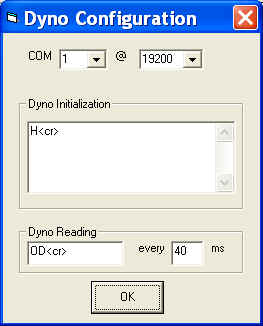
- Dyno Initialization contains the commands to set up Dyno. For example you can change dyno's torque and RPM ranges
-
Dyno Reading sends the request command to dyno at the rate
defined in interval box: Some dyno requires read command
for each pair of torque and RPM readings
-
The interval is defined as the absolute value of
the number inside the interval text box
- The minimum interval is dictated by the timer resolution of Windows.
- Positive number: Most modern instruments would prefer this setting. For example, if the interval is 50 ms, the Dyno Reading command will be sent out every 50ms, OD<cr> ..... OD<cr> ..... OD<cr>, where .... represents the interval of 50ms
- Negative number: The command strings will be sent out one character at a time at the predefined interval so that a slower instrument has enough time to process the command. For example, if the interval is 50 ms, the Dyno Reading command will be sent out one character at a time every 50ms, i.e, O....D....<cr>....O....D....<cr>....O....D....<cr>, where .... represents the interval of 50ms
-
The interval is defined as the absolute value of
the number inside the interval text box
-
<cr> represents CR (carriage return)
and <lf> represents LF (line feed)
Note: You will need to read dyno's user manual or contact the manufacturer to determine if you need CR or CR+LF to terminate a command line. According to one user's unverified account, Magtrol's command line should be ended by CR under RS-232 configuration instead of CR+LF even though the manual clearly indicates CR+LF.
- Combine Windaq channels and Torque and Speed channels generated by Dynamometers
- Selectable sign: positive number for clockwise dynamometer shaft rotation Torque, negative for counterclockwise dynamometer shaft rotation, or the opposite
- The directional input for Torque Transducer Display (Model 6400 and 3410) is ignored
- Dyno allows user configuration to change its sensitivity and range. It is the user's responsibility to set up the Min/Max value for dyno channels, or the waveform maybe outside of the chart or too weak to plot
- Support Pause/Resume
- Commented Event Marker at resume
- User annotation for each channel, including Torque and Speed channels
- Auto increment for .WDQ file name
- File size: up to 4GB
- 14-bit representation for Dyno channels
-
Custom configuration for dynamometer
-
Supported Dynamometers or Torque Displays
-
DSP6000 Dynamometer from Magtrol
-
DSP6001 Dynamometer from Magtrol
-
6200 Dynamometer from Magtrol
-
Micro Dyne System from Magtrol
-
Model 6400 Torque Transducer Display from Magtrol
-
Model 3410 Torque Display from Magtrol
-
Please suggest your favorite instrument. The instruments should be connected to a PC via RS-232 or USB/Serial Bridge
-
-
Performance and Features
-
Email/Text Messaging(SMS) Link (ID=7043)
Imagining you are using WinDaq to monitor seismic activity, and you want to be notified the as soon as the P-wave arrived so that you can prepare for the much more damaging S-wave coming soon. To do that, you can use the Digital and Alarm Output or Remote Event Note Taker's email link feature. Once the P-wave is identified, a message can be sent to your PC or smart phone immediately.
Email/Text Messaging(SMS)-enabled data acquisition, or email Link for WinDaq add-ons provides instant notification when an Alarm or Event is captured. It can also be used as periodical (keep alive) monitor
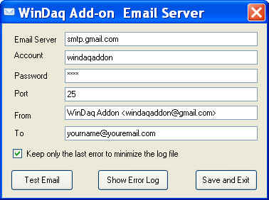
ApplicationConfiguration
You must configure the email server for WinDaq add-on before you can use the email/SMS link in Digital and Alarm Output or Remote Event Note Taker.
-
Email Server is the SMTP server. In the screen capture above, we use gmail.
-
Account is your account name. In the screen capture above, we provide a public account, windaqaddon@gmail.com, which can be used freely until you create your own one.
-
Password is the one for your Account. You don't need to enter one if you use the public account provided by us.
-
Port is the port of your SMTP server
-
From is your email ID. If you wish to use our public email account, please enter WinDaq Addon <windaqaddon@gmail.com>
-
To is your destination email address
-
SenderID is optional. If not empty, it will be added to the end of the subject line of emails for easy sorting
-
Unless you wish to see a lengthy error log, please keep the check for Keep only the last error to minimize the log file
-
Test Email to send out a "Hello World!" email to your destination email
-
Save and Exit to save the configuration
-
Please switch to your own email account as soon as possible to prevent traffic jam to our public account
-
Here is a complete list of Text Messaging (SMS) Email Address for your smart phone
-
-
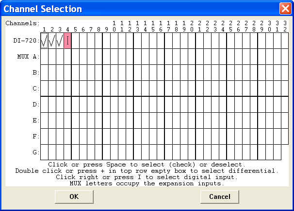
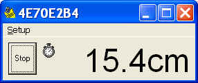
Event Counter (ID=7021)
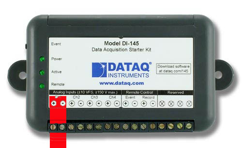
Event Counter records the number of state changes on the Event flag input or threshold-crossings from a specified channel of the device, and a math function converts the count to real results, such as converting the pulses recorded from a wheel to the actual distance a vehicle travels.
-
Two trigger sources
- Event Flag input
- This is not available to devices running non-standard HiRes firmware
- For 710 series, digital channels must be enabled at channel 17 by entering letter "I" to use this add-on; For 718B(x), digital channels must be enabled at channel 9 by entering letter "I" to use this add-on.
- Analog Channel
- This is available to ALL devices
- The Analog Channel can be any channel in Windaq's
scanlist. Must read:
The mystery of channel index!
- Event Flag input
-
Two trigger levels
- TTL trigger level for Event Flag, typical 2.6V or higher for TRUE (high) state
- Analog trigger
any level within the range of the channel
- Three triggering methods: Rising, Falling and Changing
- Software De-bouncing capability.
- Maximum count: 2,147,483,647
-
Math function
- For example, you can use #COUNT*2.2+0.25 to convert count to a real engineering result.
- WinDaq Link: While WinDaq is recording, you can send the current result to
the WinDaq file as a commented event marker
- Press "W" key to send the current reading
- Press "P" key to automatically send the reading.
- Due to the delay from the link between EventCounter and WinDaq, a minimum logging interval of 2 seconds is required before this command can be utilized
- Due to asynchronous, the timing of the comment should be considered as a reference
- A clock icon will display if this mode is accepted.
- Selectable font/background colors
- Sample rate is the same as Windaq's
- Do not enable remote options in WinDaq, or its scanning process may intercept and modify its state before we can catch it
- Double click the counter turns on/off the menu.
-
Spreadsheet compatible log file (.csv format)
- Minimum logging interval: 1 second
- Excel compatible Date and Time format
- Shows both total count (sum) and delta (difference)
- Write to log file only when there is activity (For example: there is no activity from 3:08:26 PM to 3:09:28 PM in the sample below )
-
Sample log file:
Note: there is no activity from 3:08:26 PM to 3:09:28 PM
-
Two trigger sources
-
Event Navigator for WinDaq Waveform Browser (ID=7031)
This application is the advanced event managing center for WWB to synchronize the analog waveform recorded in WinDaq and its audio/text comments. You can click on an event to jump to the specific location of a waveform when the event for inserted. If the event has audio comment created by Advanced Event , it will play back the audio comment. When WWB tracking option is checked, it follows the cursor movement of WWB and highlight/playback the comments when the cursor is on an event.
Due to its nature of being an utility for WWB, it is normally installed as a hidden add-on. Please use Windaq Add-on Manager to add it to Windaq's menu if you wish to invoke it from WinDaq Acquisition Software's add-on menu
Features of WWB Event Navigator:
- Easy access to commented event markers: Unlike WWB's event markers' dialogue box, you don't need to close the dialogue box to move the cursor to the even marker.
- Click on an audio comment, it will move the cursor on WWB as the audio comment is played back
- If EarlyMark is checked, instead of move WWB cursor to the time of the text comment is inserted, it will move the WWB cursor to the location when you start to type in the text comment
- If Track WWB is checked, when you study the waveform in WWB, it will highlight the comment when the cursor is in the region of a comment. If the comment is audio-based, it will start to play back the comment based on the location of WWB cursor.
Notes:
- Since WinDaq Waveform Browser (WWB) doesn't provide portal for
add-ons, this application is listed under WinDaq acquisition
software. There are two ways to start this applications:
- If you are using WinDaq acquisition software, you can start it from its add-on sub menu
- Or, you can run the shortcut WWB Event Navigator under Windows->Start->WinDaq group
- Due to the exclusive nature of the WWB link engine, only one copy of WWB FFT Viewr or WWB Advanced Event Navigator can be opened at any time
- If a Wdq file is being acquired to by WinDaq Acquisition software, it should be closed first before it can be opened by WWB Event Navigator
- Non-standard HiRes and packed Pro+ WinDaq files are not supported at this moment
- If .wdq file extension is not associated with WwbEventNavigator, you can start this program from Windaq\AddOn\WwbEventNavigator short cut
-
ExcelLink (ID=7007)
Excel Link supports both 32-bit and 64-bit Excel. Unlike WinDaq/XL, Excel Link stays outside of Excel while providing the data link between Windaq acquisition software and Microsoft Excel.
-
Supports both 32-bit and 64-bit version Microsoft Excel
-
You need full version of Microsoft Excel to use this feature. Click here to learn more about this requirement
-
-
Time stamp optional
-
Supports 64-bit version of Microsoft Excel, which is incompatible with WinDaq/XL
-
Channel number is a 0-based index to Windaq's scanlist. For example, if WinDaq has channel 3,4,6,7 enabled, one can enter 0 for channel 3, 1 for channel 4, 2 for channel 6 and 3 for channel 7.
-
If data should be entered by events from keyboard, timer or remote storage control, please check out
-
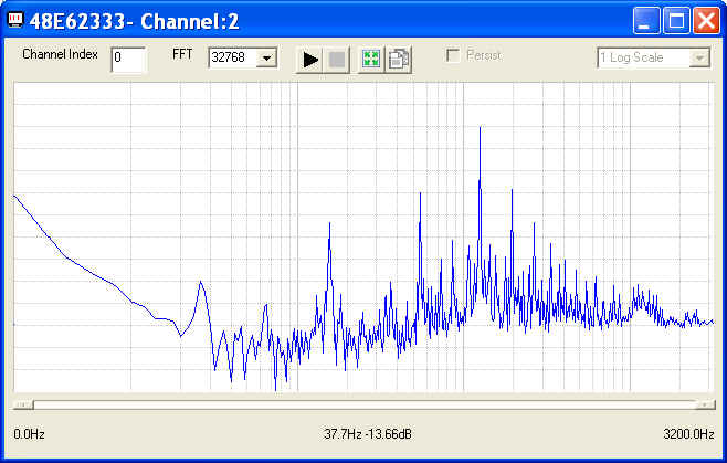
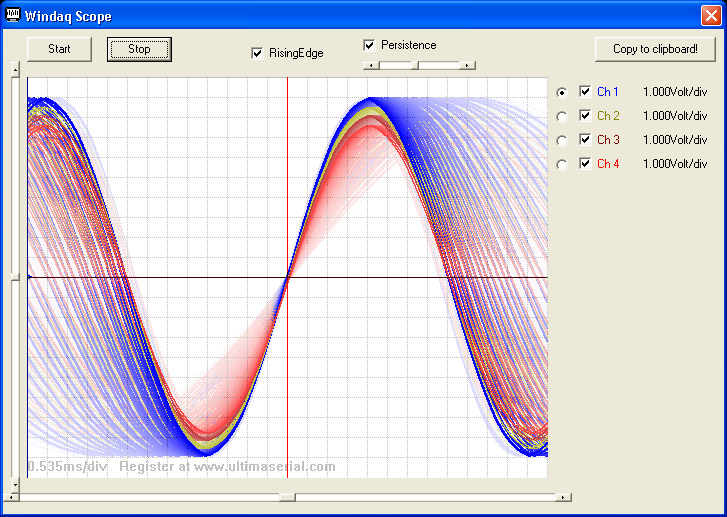
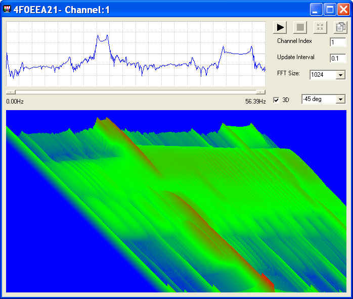
- Fast Fourier Transform II (FFT II) (ID=7017)
This is the second generation the FFT WinDaq add-on, which is based on a very powerful commercial FFT module, with multiple FFT sizes and much higher resolution.
- Multiple FFT sizes: 1024, 2048, 4096, 8192, 16384
and 32768. Please
make sure you upgrade to the latest DATAQ ActiveX if FFT generates
blank results. WinDaq activex had a glitch to deal with starter kit
and it was fixed recently.
- Due to Windaq's memory allocation approach, the following rule
should be observed if you wish to use this add-on
- For FFT size of 1024, up to 58 channels can be enabled in Windaq
- For FFT size of 2048, up to 29 channels can be enabled in Windaq
- For FFT size of 4096, up to 15 channels can be enabled in Windaq
- For FFT size of 8192, up to 7 channels can be enabled in Windaq
- For FFT size of 16384, up to 3 channels can be enabled in Windaq
- For FFT size of 32768, only 1 channel can be enabled in WinDaq (This is for registered user only)
- DC component of the signal can be removed before FFT is performed
- Due to Windaq's memory allocation approach, the following rule
should be observed if you wish to use this add-on
- True full ADC resolution
-
While acquiring spectrum, you may
- use the left mouse button to drag the waveform up and down
- double-click the left of right mouse buttons to change the scaling of the waveform.
- adjust the Analog oscilloscope-like persistence control to study the trend of the spectrum (Refer to the above screen shot for visual effect)
-
push down the right mouse button to enable a
vertical cursor to exam to the waveform.

- click on AutoSet button to bring a weak signal into sight immediately
-
Once
you stop the live frequency display, you may
- push down the left mouse button on the chart to enable a vertical cursor and drag it around to study the spectrum
- push down the right mouse button on the chart to enable a
cross hair and drag it around to study the spectrum
- Channel number is a 0-based index to Windaq's scanlist. For example, if WinDaq has channel 3,4,6,7 enabled, one can enter 0 for channel 3, 1 for channel 4, 2 for channel 6 and 3 for channel 7. Must read: The mystery of channel index!
- The display of FFT II is sizable
-
Three scaling options for the frequency axis:
-
Standard Frequency Scaling, each pixel line represents one frequency component and you may use the horizontal scroll bar to scroll the interested frequency range into view.
-
Logarithmic Frequency Scaling, to fit the full frequency range to the charting area with a logarithmic scale. This is perfect to generate a frequency response like what you see in an audio engineering chart. If Chart persist is checked, you may run a sweeping signal through the whole frequency range and see a frequency response chart of your sensor.
-
Full-fit Frequency Scaling, to fit the full frequency range to the charting area with a linear scale
-
- Intelligent Channel Select: Highlight/Select a channel in WinDaq and fire up this WinDaq add-on, and it will use the selected channel as its default channel
- Multiple FFT sizes: 1024, 2048, 4096, 8192, 16384
and 32768. Please
make sure you upgrade to the latest DATAQ ActiveX if FFT generates
blank results. WinDaq activex had a glitch to deal with starter kit
and it was fixed recently.
-
FFT Viewer for WinDaq Waveform Browser (WWB) (ID=7030)
FFT Viewer for WinDaq Waveform Browser (WWB) is a live FFT viewer for WWB to provide synchronized display for up to 16 analog waveforms recorded in WinDaq and its counterpart in the frequency domain.Due to its nature of being an utility for WWB, it is normally installed as a hidden add-on. Please use Windaq Add-on Manager to add it to Windaq's menu if you wish to invoke it from WinDaq Acquisition Software's add-on menu
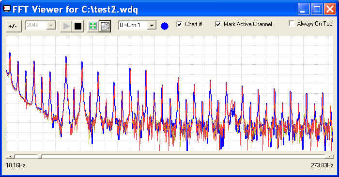
Features of FFT Viewer for WinDaq Waveform Browser:-
Supported FFT sizes: 512, 1024, 2048, 4096, 8192, 16384 and 32768
-
Up to 16 WWB channels can be monitored at the same time
-
The FFT frame starts at the WWB cursor point
-
All important configurations are retained at the end of a session for easy reopening
-
BestFit button brings the active channel to full screen display
Notes:
- Since WinDaq Waveform Browser (WWB) doesn't provide portal for
add-ons, this application is listed under WinDaq acquisition
software. There are two ways to start this applications:
- If you are using WinDaq acquisition software, you can start it from its add-on sub menu
- Or, you can run the shortcut WWB FFT Viewer under Windows->Start->WinDaq group
- Due to the exclusive nature of the WWB link engine, only one copy of WWB FFT Viewr or WWB Advanced Event Navigator can be opened at any time
- If a Wdq file is being acquired to by WinDaq Acquisition software, it should be closed first before it can be opened by WWB FFT Viewer
- Non-standard packed Pro+ WinDaq files, .WDC and .WDH are not supported at this moment
-
-
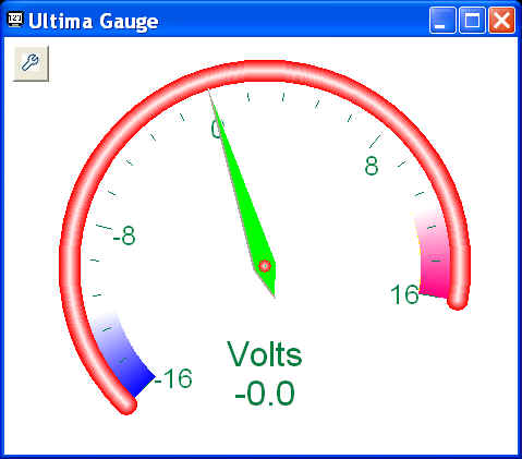
Gauge (ID=7034)
Gauge combines the power of WinDaq Meter and Calculated WinDaq Meter to provide an analog instrumentation gauge display.
- Intelligent Channel Select: Highlight/Select a channel in WinDaq and invoke WinDaq->View->Add-ons->Magic Meter, and it will use the selected channel as its default channel when it is not in calculated channel mode.
- Move the mouse to the left edge of the display to reveal the configuration button.
-
Like Magic Meter, double click on its face will remove the border
and change to its predefined transparency setting (see the screen
capture below)
-
Data Window to perform the following operations
- None: The last reading
- Average: Average all readings in the data window before presenting it
- Minimum: Display only the minimum reading within the data window
- Maximum: Display only the maximum reading within the data window
- RMS: Perform RMS for all readings within the data window
- AC RMS: Average all readings and use the result as offset. Remove the offset of all readings then perform RMS
- Calculated Channel with the following features:
- Must read: The mystery of channel index!
- Operators include: +, -, *, /, ^, %, &, |, !, >, >=, <, <=, !=, ==
- Functions include: abs, floor, hex, round, if, avg, bin, log, sqrt, ceil, log10, sum, max, min, acos, asin, atan, sin, sinh, cos, tan, cosh, tanh
- To use the reading from a channel, use #n. For example, #0 is the reading from the first enabled channel in Windaq
- To access the sample rate, use #@.
-
You can use earlier readings to form a more complicated
math expression. To do so, add a letter after #, and alphabet
order of the letter represents the delay, Such as:
- #0 is the reading from channel 0
- #A0 is the reading from channel 0, one scan earlier
- #B1 is the reading from channel 1, two scans earlier
- Readings from up to 26 scans earlier can be used, for example, #Z0.
- For example: use ( #0-#A0)*#@ to form a two-point derivative
- Support non-English (United States) Regional and Language options
- To use the data-window results, use #min, #max, #ave, #rms and #acrms to represent Min/Max/Ave/RMS/ACRMS in the expression, i.e, #acrms0 take the AC_RMS of channel 0.
- The calculated result is presented AS IS. To round to a certain position, please use round, floor, or ceil functions. For example, if the format ###.## is preferred, you can use round(result*100)/100, where result should be replaced by your math expression
- Fully programmable palette, gauge begin/end degree, min/max,
normal/high/low rang and display decimals for better visual effect
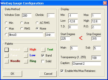
- Note: Since they can be customized and their values retained, the Min and Max may not match the dynamic range of the channel you are monitoring unless it is the first time Gauge is invoked.
-
Min/Max retainer records the Minimum and Maximum readings
since its started or the last time the Gauge was configured.
Please note, since Gauge does NOT monitor every data point
acquired by the device, the min/max only reflects all the values
captured by Gauge.
- To reset Min/Max retainers, enter Gauge Configuration and
exit via OK button
- To reset Min/Max retainers, enter Gauge Configuration and
exit via OK button
Highlights
-
Histogram (ID=7015)
It provides live histogram as well as a log file on any channel you specified. It is a great tool to monitor the long-term stability and noise distribution of sensors.
- Bin numbers: from 32 to 16384, matching the single LSB in standard WinDaq resolution
- Bin depth: 2147483640
- Chart width: up to 512 bins
- Cursor to identify a position/bin with annotation in engineering unit
- Channel number is a 0-based index to Windaq's scanlist. For example, if WinDaq has channel 3,4,6,7 enabled, one can enter 0 for channel 3, 1 for channel 4, 2 for channel 6 and 3 for channel 7. Must read: The mystery of channel index!
- Excel compatible log file (.CSV format)
- Horizontal scroll bar to position the histogram when total bin# exceed the chart width
- Intelligent Channel Select: Highlight/Select a channel in WinDaq and fire up this WinDaq add-on, and it will use the selected channel as its default channel
-
Retainable Settings: Bin count, Bin Offset, Log
file name
-
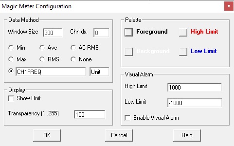
Magic Meter (ID=7033)
Magic Meter combines the power of Regular WinDaq Meter and Calculated WinDaq Meter to provide a text-based meter display with translucent background so that it can be embedded into DATAQ's WinDaq acquisition software
Highlights
-
Intelligent Channel Select: Highlight/Select a channel in WinDaq and invoke Windaq->View->Add-ons->Magic Meter, and it will use the selected channel as its default channel (see video demo above) when it is not in calculated channel mode.
-
Move the mouse to the left edge of the display to reveal the configuration button

-
Click on the configuration button to adjust the setting
- Double click on the display to switch to transparent mode
-
Data Window to perform the following operations
- None
- Average: Average all readings in the data window before presenting it
- Minimum: Display only the minimum reading within the data window
- Maximum: Display only the maximum reading within the data window
- RMS: Perform RMS for all readings within the data window
- AC RMS: Average all readings and use the result as offset. Remove the offset of all readings then perform RMS
- Calculated Channel with the following features:
- Operators include: +, -, *, /, ^, %, &, |, !, >, >=, <, <=, !=, ==
- Functions include: abs, floor, hex, round, if, avg, bin, log, sqrt, ceil, log10, sum, max, min, acos, asin, atan, sin, sinh, cos, tan, cosh, tanh
- To use the reading from a channel, use #n. For example, #0 is the reading from the first enabled channel in Windaq
- To access the sample rate, use #@.
-
You can use earlier readings to form a more complicated
math expression. To do so, add a letter after #, and alphabet
order of the letter represents the delay, Such as:
- Must read: The mystery of channel index!
- #0 is the reading from channel 0
- #A0 is the reading from channel 0, one scan earlier
- #B1 is the reading from channel 1, two scans earlier
- Readings from up to 26 scans earlier can be used, for example, #Z0.
- For example: use ( #0-#A0)*#@ to form a two-point derivative
- Support non-English (United States) Regional and Language options
- To use the data-window derived results, use #min, #max, #ave, #rms and #acrms to represent Min/Max/Ave/RMS/ACRMS in the expression, i.e, #acrms0 take the AC_RMS of channel 0.
- The calculated result is presented AS IS. To round to a certain position, please use round, floor, or ceil functions. For example, if the format ###.## is preferred, you can use round(result*100)/100, where result should be replaced by your math expression
- The math equation must be valid even you don't plan to use it now
- Displays channel unit
- Fully programmable palette for better visual effect when
superimposing magic meter to Windaq.
- The background should match Windaq's background
- Foreground should match Windaq's background if only warning display is needed to capture attention
-
Limitations
- Although the meter seems to embed inside WinDaq, it is NO, when you move WinDaq's window around or add/subtract channels, it will NOT follow your action.
- The display is right-justified to align the units all the time, so make sure you make the width of the windows long enough to display ALL digits
-
-
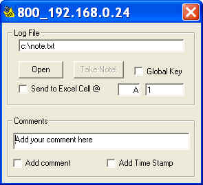
Manual Note Taker with Excel Link (ID= 7011)
A handy add-on to record the reading of all channels to a text file or Excel spreadsheet with a single click.The name NOTE TAKER was derived
from the add-on's original application, in which it logs to a notepad
compatible text file. Live Excel link was added per users' request.
-
If log file extension is .csv, the file can be opened by spreadsheet program, such as Excel, immediately
-
Excel Link
-
Supports both 32-bit and 64-bit version Microsoft Excel
-
You need full version of Microsoft Excel to use this feature. Click here to learn more about this requirement.
-
-
If Send to Excel Cell option is checked, the readings will be sent to Excel immediately
-
-
To get stable readings, increase the average length in WinDaq.
-
Global Key option. When checked, you can use Alt+Ctrl+N (default) to take notes even when the addon is out of focus, ie, minimized or behind WinDaq.
-
The global keys stored in c:\windows\wdqnotetaker.ini can be reprogrammed
-
Open c:\windows\wdqnotetaker.ini and you will see multiple sections for different WinDaq configurations
-
Under the section matching the device, you will see something like this
NoteTakerKey=78
HKey0=17
HKey1=18 -
The numbers are Microsoft Virtual Key codes. The HKey0 and HKey1 are the two hot keys to mark the commands, which are Ctrl and Shift by default
-
You can use change it to avoid conflict with other Windows application or add a new sets of command different Devices
-
For example, assign 49 to NoteTakerKey for WinDaq device 1 and 50 to NoteTakerKey for WinDaq device 2 , you can use Alt+Ctrl+1 to send the data from Device 1 to Excel book 1 and use Alt+Ctrl+2 to send the data from Device 2 to Excel book 2
-
-
Excel compatible time stamp format to calculate time difference between events (See below)
chn0(Volt) chn1(Volt) chn2(Volt) chn3(Volt) Comment TimeStamp 0 -0.0078125 -0.0078125 -0.0078125 test1 7/13/2010 14:37 0 -0.0078125 -0.0078125 -0.0078125 test2 7/13/2010 14:37 0 -0.015625 0 0 7/13/2010 14:38 -0.0078125 -0.015625 -0.0078125 -0.0078125 7/13/2010 14:38 -0.0078125 -0.0078125 -0.0078125 -0.0078125 TimeStamp disabled 0 -0.015625 -0.0078125 0 TimeStamp disabled 0 -0.015625 -0.015625 0 TimeStamp disabled -0.0078125 -0.015625 -0.0078125 0.0078125 TimeStamp disabled 0.0078125 -0.015625 0.0078125 0 TimeStamp disabled 0 -0.015625 0 0 TimeStamp disabled -0.0078125 -0.015625 0 0.0078125 TimeStamp disabled 0 0 -0.0078125 0 TimeStamp disabled
-
-
MySQLLink (ID=7014)
This is based on DATAQ's WindaqMySQL example, and we turn it into a true WinDaq add-on. VB source codes are included. Because this is not from us, we can not verify its functionality nor provide any warranty or support, please refer to its source codes if you have any concern. For this very reason, MySQLLink is installed as an invisible add-on by default, please use WinDaq add-on Manager to enable it if you wish to give it a try.
Since the connection to MySQL may not be very fast, do not use it with high acquisition sample rate.
-
OpenOfficeCalc Link (ID=7013)
This WinDaq add-on provides a live link between WinDaq and OpenOffice.org's Calc . Due to its low popularity, OpenOffice Calc is normally installed as a hidden add-on. Please use Windaq Add-on Manager to add it to Windaq's menu if you wish to invoke it from WinDaq Acquisition Software's add-on menu. VB source codes are included to demonstrate how to write a VB program to export data to OpenOffice.Calc directly If you wish to convert the program to Visual Basic 2008 Express Edition (VBX2008), check this out
- Single click sends data directly from WinDaq to OpenOffice.org Calc spread sheet
- Channel number is a 0-based index to Windaq's scanlist. For example, if WinDaq has channel 3,4,6,7 enabled, one can enter 0 for channel 3, 1 for channel 4, 2 for channel 6 and 3 for channel 7.
- If data should be entered by events from keyboard, timer or remote storage control, please check out
-
Time stamp optional
-
Oscilloscope (ID=7008)
Provides powerful analog oscilloscope like display with easy trigger management.
- Display up to 16 waveforms in any combination
- Waveforms can be move freely within the windows for easy comparison
- Trigger display on any enabled waveform
- Analog oscilloscope-like persistence control helps to study the trend of the waveforms (Refer to the above screen shot for visual effect)
- Easy control for trigger-slope, trigger-level and trigger-point
- One click to copy the waveforms to clipboard
- Click anywhere in the grid first, and you can use mouse wheel to change the scaling of the trigger channel (channel 1 in the above configuration). If you need to change the scaling for another channel, make it the trigger channel first.
-
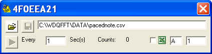
Paced Note Taker with Excel Link (ID=7019)
Timer paced note taker allows user to record data to a spreadsheet file or Excel at a much slower pace while WinDaq displaying the waveform at high speed. Minimum interval 0.5 second
The name NOTE TAKER was derived from
the add-on's original application, in which it logs to a notepad
compatible text file. Live Excel link was added per users' request.
-
If log file extension is .csv, the file can be opened by spreadsheet program, such as Excel, immediately
-
Excel Link
-
Supports both 32-bit and 64-bit version Microsoft Excel
-
You need full version of Microsoft Excel to use this feature. Click here to learn more about this requirement.
-
-
If Send to Excel Cell option is checked, the readings will be sent to Excel immediately
-
-
Excel compatible time stamp format to calculate time difference between events, see example below
chn0(Volt) chn1(Volt) chn2(Volt) chn3(Volt) TimeStamp 0 0 -0.015625 0 14:38:32 -0.0078125 -0.0078125 -0.0078125 0 14:38:34 -0.0078125 -0.015625 -0.0078125 -0.015625 14:38:36 -0.0078125 0 -0.0078125 -0.0078125 14:38:38
-
-
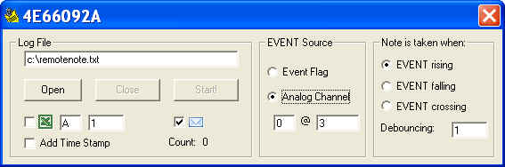
Remote Event Controlled Note Taker with Excel Link (ID=7012)
This add-on records the reading of all channels to a text/spreadsheet file or Excel directly when the Event flag is changed or the reading on a specified channel cross the threshold.
Sample ApplicationAutomatically logs the cargo weight while it is being moved through a conveyor belt.
Setup:
-
At the end of the scale, add a mechanical switch that connects to the Event inputs or a pre-specified channel (a pull-up is needed in this case)
-
Run WinDaq and this add-on
-
The cargo will be sent to the scale through a conveyor belt
-
The cargo will trip the switch set up in step 1
-
The weight will be logged to Excel spread sheet as well as a specified text file (as backup, in case Excel was closed accidentaly by the user)


-
Two trigger sources
- Event Flag input
- Same as the push-button on DI-145 and 149
- The EVENT flag on the most devices has internal pull-up
- This is not available to devices running non-standard HiRes firmware
- For 710 series, if Event Flag is used as trigger source, the digital channels must be enabled at channel 17 by entering letter "I" to use this add-on; For 718B(x), digital channels must be enabled at channel 9 by entering letter "I" to use this add-on
- Analog Channel
- This is available to ALL devices
- The Analog Channel can be any channel in Windaq's scanlist.
Must read:
The mystery of channel index!
- Trigger methods include rises, falls or changes.
- Optional: software de-bouncing. In the above capture, 2 stable readings are required before entering trigger modes
- Event Flag input
-
Two trigger levels
- TTL trigger level for Event flag
- Any level within the range of the channel for Analog Channel trigger
- If log file extension is .csv, the file can be opened by spreadsheet program, such as Excel, immediately
-
Excel Link
-
Supports both 32-bit and 64-bit version Microsoft Excel
- You need full version of Microsoft Excel to use this feature.
- Click here to learn more about this requirement.
- If Send to Excel Cell option is checked, the readings will be sent to Excel immediately
-
Supports both 32-bit and 64-bit version Microsoft Excel
-
SMS and Email Link
- Sends out email when an event is captured
- Use SMS/Email Manager to configure it first
- Since all data points are examined during the operation, it may not keep up with high-speed operation
- Time stamp is added to every row of data, with 1 second resolution.
- Do not enable remote options in WinDaq, or its scanning process may intercept and modify its state before we can catch it
-
Excel compatible time stamp format to calculate time
difference between events, see example below:
chn0(Volt) chn1(Volt) chn2(Volt) chn3(Volt) TimeStamp 0 -0.0078125 -0.015625 0.015625 7/13/2010 14:39 0 -0.0078125 -0.0078125 0 7/13/2010 14:39 -0.0078125 0 -0.0078125 0 7/13/2010 14:39 -0.0078125 -0.0078125 -0.0078125 0 7/13/2010 14:39 0 -0.015625 -0.0078125 0 7/13/2010 14:39 0 -0.0078125 0 0 7/13/2010 14:39 0 -0.0078125 -0.0078125 -0.0078125 7/13/2010 14:39 0 -0.0078125 0 -0.0078125 7/13/2010 14:39
-
-
Spectrogram II (ID=7018)
This is the second generation the original Spectrogram WinDaq add-on based on a very powerful commercial FFT module, with multiple FFT sizes, much higher resolution and adjustable spectrum displays
- Multiple FFT sizes: 1024, 2048, 4096 and 8192. Please make sure
you upgrade to the latest DATAQ ActiveX if FFT generates blank
results. WinDaq activex had a glitch to deal with starter kit and it
was fixed recently.
- Due to Windaq's memory allocation approach, the following rule
should be observed if you wish to use this add-on:
- For FFT size of 1024, up to 58 channels can be enabled in Windaq
- For FFT size of 2048, up to 29 channels can be enabled in Windaq
- For FFT size of 4096, up to 15 channels can be enabled in Windaq
- For FFT size of 8192, up to 7 channels can be enabled in Windaq
- DC component of the signal can be removed before FFT is performed
- Due to Windaq's memory allocation approach, the following rule
should be observed if you wish to use this add-on:
- True full ADC resolution
- For the Spectrum display on top
- Single click on AutoSet button will adjust the scale to bring
a weak signal into sight immediately
- While acquiring spectrum, you may
- use the left mouse button to drag the waveform up and down
- double-click the left or right mouse button to change the scaling of the waveform.
- push down the right mouse button to enable a vertical
cursor to exam to the waveform.
- Once you stop the live frequency display, you may
- push down the left mouse button on the chart to enable a vertical cursor and drag it around to study the spectrum
- push down the right mouse button on the chart to enable a
cross hair and drag it around to study the spectrum
- Single click on AutoSet button will adjust the scale to bring
a weak signal into sight immediately
- For the Waterfall display on the bottom
- The waterfall display follows the scaling and offset of the spectrum display on top
- You may also click the left mouse button on the waterfall chart to enable a crosshair to show the frequency/elapsed time
-
Regarding the update interval
- The update interval is controlled by Windows's Timer, which is
- 15.6ms minimum by default under Windows 7
- 20ms minimum by default under Windows XP
- The power of PC's CPU also determines if the minimum update interval is achievable or not
- Actual (averaged) update interval will be displayed on the spectrogram is started
- Actual (averaged) update interval will be used to calculated the elapsed time for the cross-hair
- The update interval is controlled by Windows's Timer, which is
- Channel number is a 0-based index to Windaq's scanlist. For example, if WinDaq has channel 3,4,6,7 enabled, one can enter 0 for channel 3, 1 for channel 4, 2 for channel 6 and 3 for channel 7. Must read: The mystery of channel index!
-
You may
also click on the waterfall chart to enable a crosshair to show
the frequency/elapsed time
- The elapsed time is of approximation only since the performance of the spectrogram is based on your PC's power
- The frame of Spectrogram II is sizable, and the two charts will adjust accordingly
- Intelligent Channel Select: Highlight/Select a channel in WinDaq and fire up this WinDaq add-on, and it will use the selected channel as its default channel
- Multiple FFT sizes: 1024, 2048, 4096 and 8192. Please make sure
you upgrade to the latest DATAQ ActiveX if FFT generates blank
results. WinDaq activex had a glitch to deal with starter kit and it
was fixed recently.
If channel index number is required as user input for a WinDaq add-on, please enter the 0-based index to Windaq's scanlist.
Exception: For DI-71x and DI-155, the digital channel always takes up the first index if it is enabled, even though it is NOT the first member in the scanlist!
DI-710, 718, 715 or DI-155 All others Any of the following conditions is true:
- Digital Channel is enabled, where digital channel is noted by "I" in the channel selection grid
- WinDaq->Option->Remote Events is checked
- WinDaq->Option->Remote Storage is checked
All of the following conditions are true:
- Digital Channel is NOT enabled
- WinDaq->Option->Remote Events is not checked
- WinDaq->Option->Remote Events is not checked
Any configuration 0 is always the digital channel 0 is the first channel in the scanlist 0 is always the first channel in the scanlist Example: WinDaq has channel 3,4,6,7 and I (digital) and R (Rate) enabled.
Since digital channel I always takes the first spot in the data stream even though it is the last member in the scanlist, one has to enter 0 for the digital channel, 1 for channel 3, 2 for channel 4, 3 for channel 6 and 4 for channel 7 and 5 for channel R .
Example: WinDaq has channel 3,4,6,7, R (Rate) and C (Counter) enabled.
Since no digital channel is enabled, we have 0 for channel 3, 1 for channel 4, 2 for channel 6, 3 for channel 7, 4 for for channel R and 5 for channel C.
Example: WinDaq has channel 3,4,6,7 and I (digital) enabled.
Since the digital channel does not affect the index, one enters 0 for channel 3, 0 for channel 4, 2 for channel 6, 3 for channel 7 and 4 for the digital channel.
General Error Message
If you manually remove WinDaq add-on file folder, which is C:\WDQFFT by default, without removing the entries in TPDATAQ.INI. You will run into some of the following errors
"Cannot execute C:\WDQFFT\addonlaunch.exe.EXE, WinExec returned 3." when you start WinDaq.
This is caused by the missing batch launcher to start multiple add-ons after WinDaq starts
You may continue WinDaq by clicking on the OK button
To fix the error, you may either reinstall WinDaq add-on or edit TPDATAQ.INI and remove the TOOLS section totally.
"Cannot execute C:\WDQFFT\??????.EXE, WinExec returned 3." when you start an add-on, where ?????? is the executable of the selected add-on
This is caused by the missing add-on executable
You may continue WinDaq by clicking on the OK button
To fix the error, you may either reinstall WinDaq add-on or edit TPDATAQ.INI and remove the TOOLS section totally.
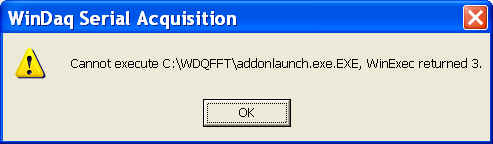
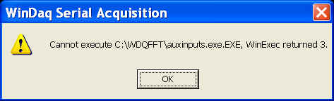
Last update: 05/01/12
© www.UltimaSerial.com